POWERHEAD
Remove the small powerhead screw at rear.
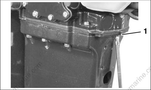
- Rear small powerhead screw 002160
Remove remaining four small powerhead screws, six large powerhead screws, and the upper mount screws.
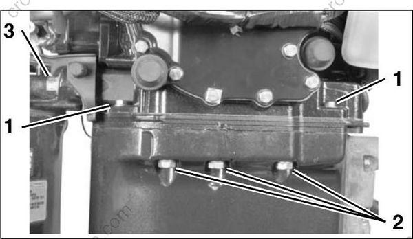
- Small powerhead screws
- Large powerhead screws
- Upper mount screws
002153
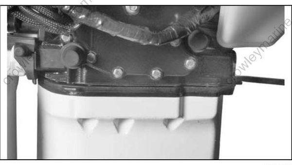
Use a suitable tool to carefully separate the powerhead from exhaust housing.
002161
IMPORTANT: Do not damage the powerhead or exhaust housing mating surfaces.
Systems Removal
To simplify reassembly and wiring installation, lay out the various screws and clamps in the order of their proper location.
To simplify reassembly and wiring installation, lay out the various screws and clamps in the order of their proper location.
Remove the electric starter. Refer to Starter Removal on p. 119.
Remove the oil tank. Refer to Oil Tank Assembly on p. 173.
Remove fuel pump assemblies, fuel manifolds, and filter. Refer to FUEL COMPONENT SERVICING on p. 146.
Remove EMM, then electrical harness assembly. Label connectors for reassembly locations. Refer to EMM SERVICING on p. 74.
Remove flywheel and stator. Refer to FLYWHEEL AND STATOR SERVICING on p. 114.
Remove ignition coils and fuel injectors. Refer to IGNITION COIL SERVICING on p. 116 and Fuel Injector Service on p. 150.
IMPORTANT: Mark injectors for cylinder location before removal. All injectors must be installed in their original location. Improper injector installation can result in powerhead failure.
Remove all oil distribution and recirculation hoses.
Remove throttle linkage. Refer to Throttle Linkage Removal on p. 198. Remove shift linkage. Refer to Shift Linkage Removal on p. 198.
Remove the throttle body and reed plate assemblies. Refer to Intake Manifold Service on p. 154.
Remove pressure valve assembly. Refer to PRESSURE RELIEF VALVE SERVICING on p. 187.
Throttle Linkage Removal
Remove throttle cam and throttle lever.
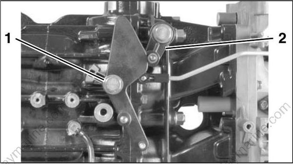
2-Cylinder Models
- Throttle lever screw
- Throttle return lever
002245
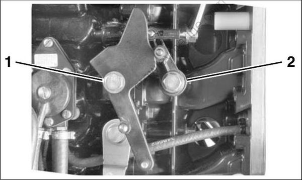
3-Cylinder Models
- Throttle cam screw
- Throttle lever screw
002257
Throttle Linkage Removal
Remove shoulder screw from shift arm and retaining screw from shift rod lever.
Remove the cotter pin and washer holding the shift shaft (2-cylinder models).
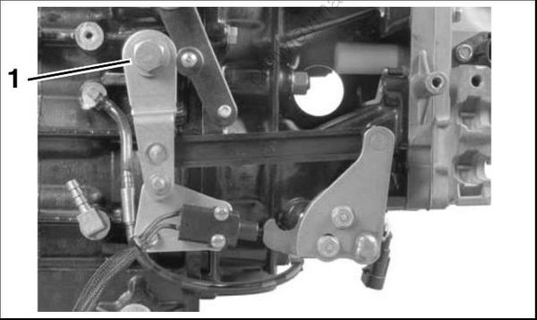
- Shift lever screw 002250
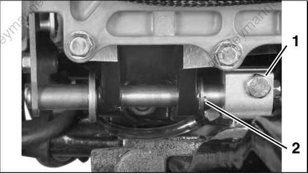
- Shift rod lever screw
- Cotter pin
002246
Slide entire shift linkage assembly from crank case.
Remove the ball, guide, and spring of the shift detent assembly from the crankcase.
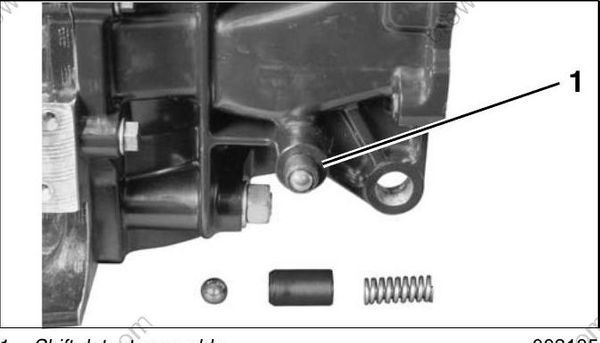
- Shift detent assembly 002135
Crankcase Disassembly
Remove screws and carefully pry off exhaust side water cover.
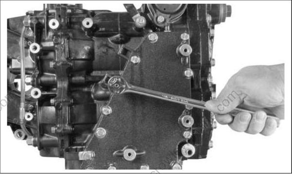
002234
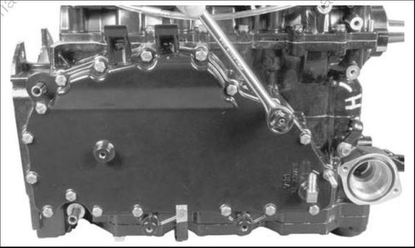
002124
Wear safety glasses to avoid injury.
Use a 1/8 in. diameter pin punch to push crank
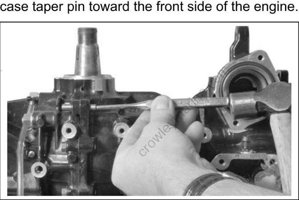
002232
IMPORTANT: Do not use a tapered punch or any other tool that could jam in or damage the taper bore when removing the pin. Remove crankcase flange screws.
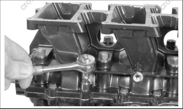
002137
Loosen in stages and remove the main bearing nuts and washers.
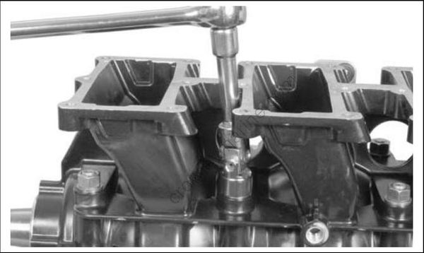
002138
Separate crankcase and cylinder block. It may be necessary to tap on crankshaft with a rawhide or rubber mallet to loosen.
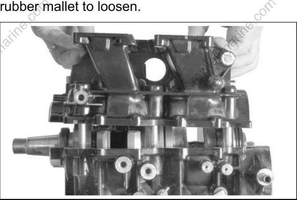
002252
Cylinder Head Removal
Remove thermostat cover and thermostat assembly. Refer to THERMOSTAT SERVICING on
p. 186.
Loosen in stages and remove cylinder head screws. Remove the cylinder head. Discard thermostat seal and O-rings.
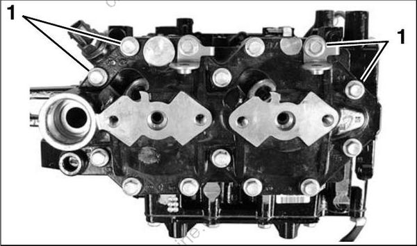
- Cylinder head screws 007850
Connecting Rods and Pistons
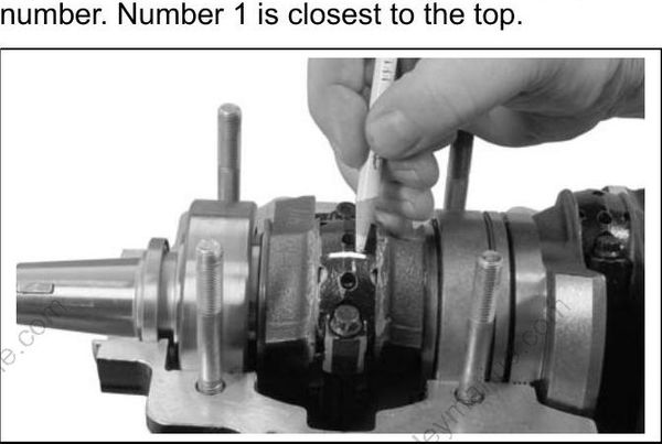
Use a permanent marker to identify each connecting rod cap, connecting rod, and piston by cylinder number. Number 1 is closest to the top.
002140
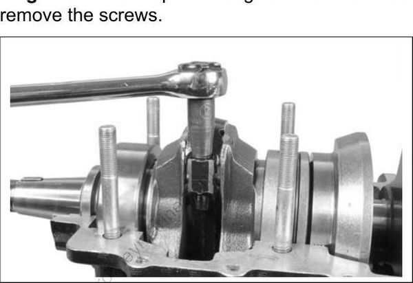
Use Torquing Socket, P/N 331638, to loosen in stages the rod cap retaining screws. DO NOT remove the screws.
002123
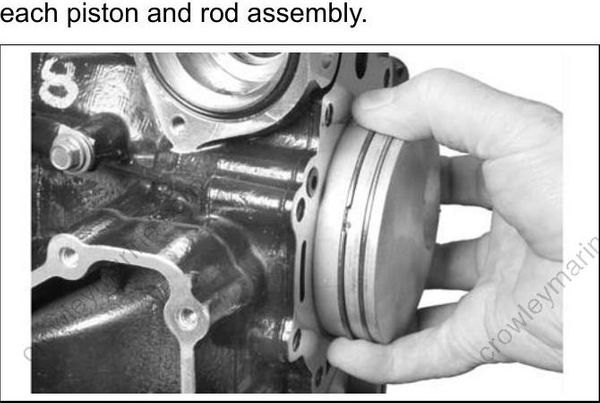
Use one hand to support the piston, and remove the rod cap screws with your other hand. Remove each piston and rod assembly.
002141
Reattach each rod cap to its rod as soon as the piston is removed. Each cap is unique and can only be installed on its mated rod. Do not allow rod to contact inside surface of cylinder or crankshaft.
IMPORTANT: Identify all internal components so that if reused, they can be reinstalled in their original positions.
Repeat steps for each remaining piston and connecting rod.
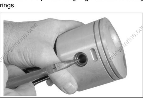
Use an appropriate ring expander to remove all piston rings from pistons. Discard the rings.
Wear safety glasses to avoid injury.
002054
002046
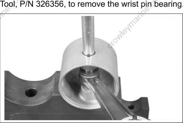
The wrist pin fit is loose on both sides. Push the wrist pin through to free the piston from the connecting rod. If necessary, use Wrist Pin Pressing Tool, P/N 326356, to remove the wrist pin bearing.
002047
Be careful not to lose any of the 28 needle bearings or the two wrist pin washers. Do not mix bearings with those from another cylinder. If any of the bearings are worn or lost, replace all 28 bearings during reassembly.
Crankshaft Removal
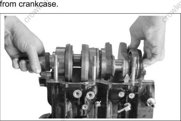
Carefully lift crankshaft straight up and remove from crankcase.
002263
Remove upper seal from crankshaft. Discard the seal. A new upper seal must be installed on assembly.
Remove the upper main bearing.
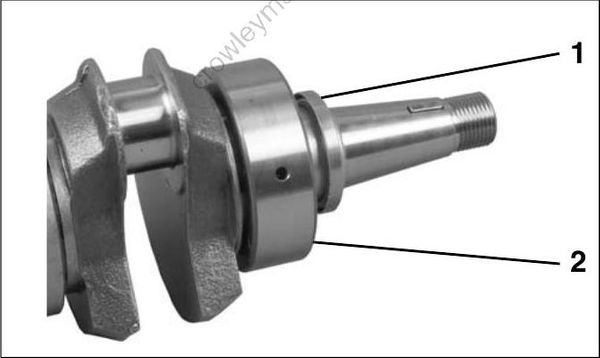
- Upper oil seal
- Upper main bearing
002034
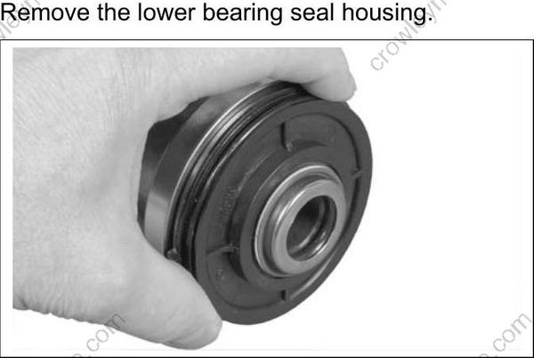
Remove the lower bearing seal housing.
002042
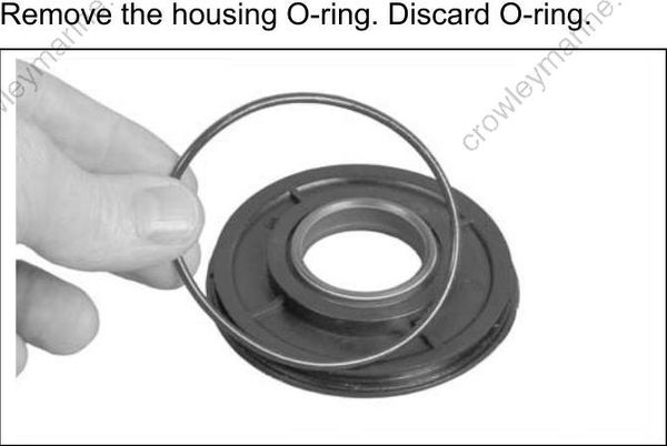
Remove the housing O-ring. Discard O-ring.
002044
Use a punch to remove the housing seal. Discard seal.
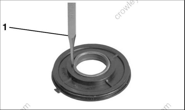
- Punch 002053
Inspect housing and replace if necessary.
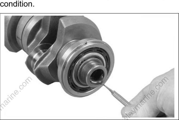
Remove the O-ring from crankshaft sleeve and inspect it. Replace the O-ring if it is not in good condition.
002040
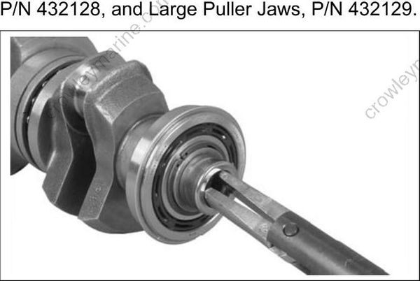
Inspect the crankshaft sleeve and replace if necessary. To remove the sleeve, use Slide Hammer, P/N 432128, and Large Puller Jaws, P/N 432129.
002041
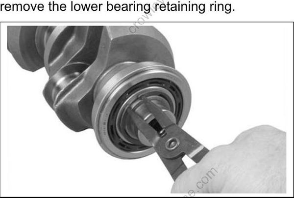
Remove the lower main bearing only if it needs to be replaced. Use external retaining ring pliers to
002039
IMPORTANT: If the lower main bearing is removed from the crankshaft, it must be discarded. DO NOT reuse it.
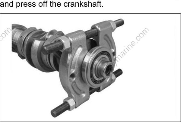
Use a bearing separator to support the bearing, and press off the crankshaft.
002052
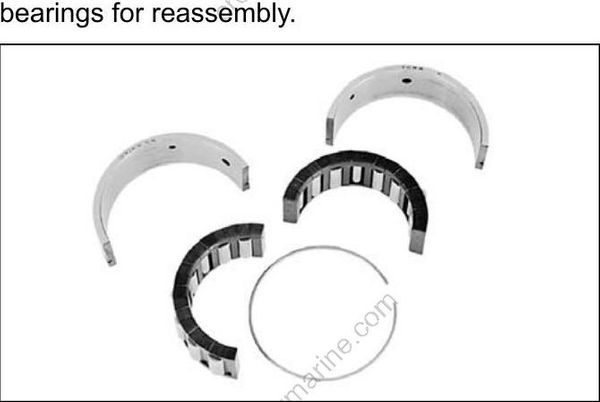
Remove center main bearings and split sleeves for inspection. DO not mix parts. Note location of bearings for reassembly.
24381