POWERHEAD ASSEMBLY
IMPORTANT: Proceed slowly. Make no forced assemblies unless a pressing operation is called for. All internal components must be perfectly clean and lightly coated with outboard lubricant.
IMPORTANT: Use new wrist pin retaining rings, gaskets, seals, and O-rings during assembly.
Crankshaft Assembly
Oil the end of the crankshaft. Use Crankshaft Bearing/Sleeve Installer, P/N 338647, and place a new lower main bearing onto crankshaft with lettered side facing the tool. Install bearing until it seats on the crankshaft.
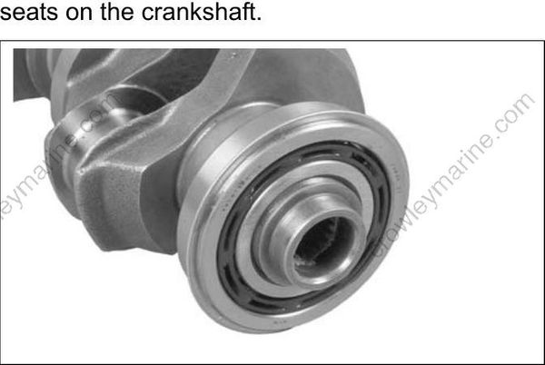
Oil the end of the crankshaft. Use Crankshaft Bearing/Sleeve Installer, P/N 338647, to drive a new sleeve onto the crankshaft until the installer
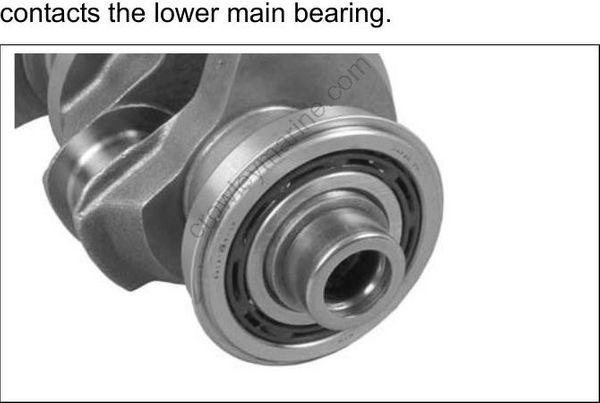
If the installer sticks on the sleeve after installation, thread Slide Hammer, P/N 391008, into installer and pull it off.
IMPORTANT: Inspect sleeve after installation. Sleeve must not be used if surface is damaged.
Use retaining ring pliers to install bearing retaining ring with sharp edge facing away from bearing.
Lubricate a new driveshaft O-ring and lightly lubricate crankshaft splines with Molt Lube Install O-ring in sleeve.
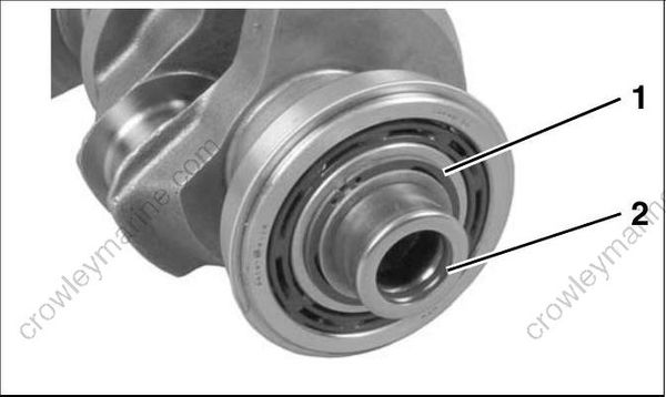
- Bearing retaining ring
- O-ring
Lubricate the center main bearings and split sleeves with outboard lubricant and install them in their original positions. The split sleeve ring grooves must face toward driveshaft (lower) end of crankshaft when installed.
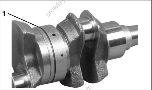
- Groove toward driveshaft end 002032
Lightly coat the outside edge of a new lower housing seal with Gasket Sealing Compound. Press against outer case of the seal to install seal in the
lower housing with extended lip facing down. Lubricate seal lip with Triple Guard grease.
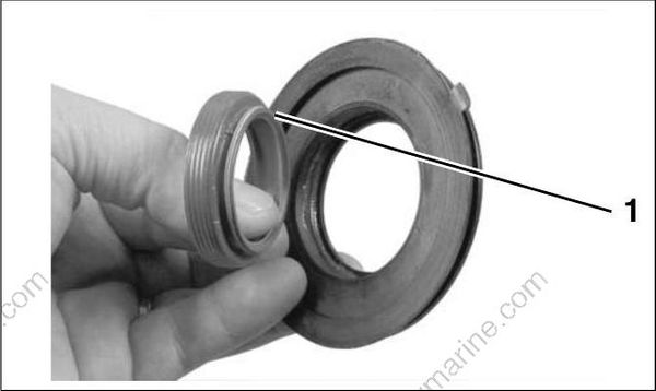
- Seal lip 002036
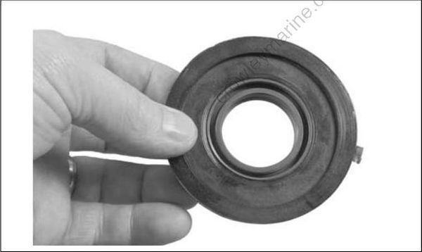
002037
Install a new O-ring on the lower housing. Before installing crankshaft into cylinder block, apply a thin coat of Gasket Sealing Compound to outer edge of O-ring.
Place lower seal housing on crankshaft.
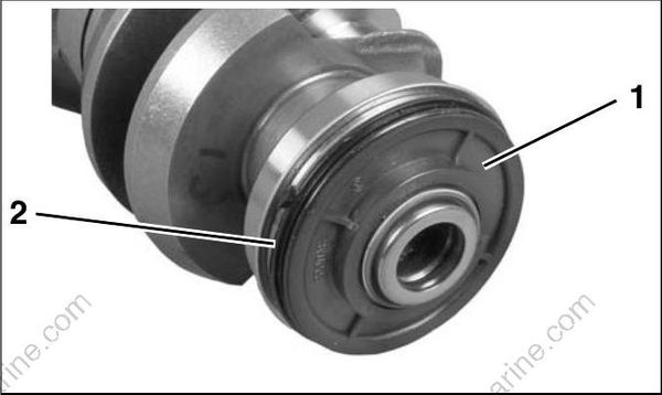
- Lower seal housing
- O-ring
002038
Lubricate upper main bearing with outboard lubricant and install on crankshaft.
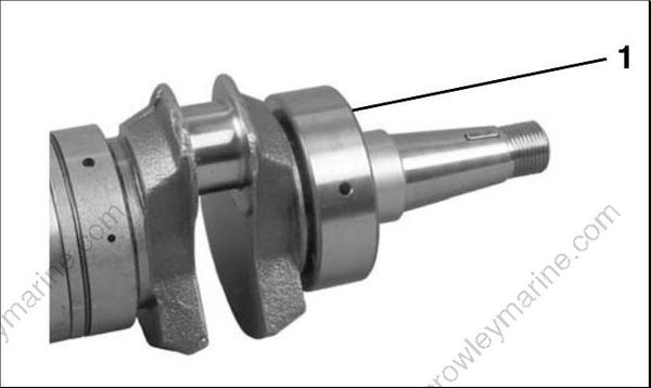
- Upper main bearing 002033
Pack lip of upper oil seal with Moly Lube. Place seal on crankshaft with lip down and enclosed face up. Do not apply sealer to outside edge of the seal.
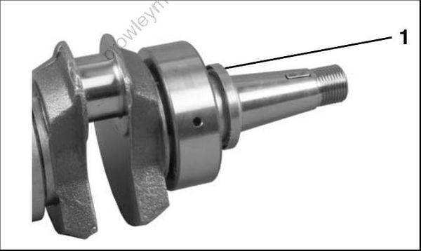
- Upper oil seal 002034
Pistons and Connecting Rods
It is very important that the pistons in this engine are installed in the correct location and direction. Engine damage will occur if installed incorrectly.
New pistons are stamped “EXH.” This marking should be turned toward the exhaust side of the block. The splash bowl on the dome of the piston will be located toward the top and starboard side of the block.

- Exhaust side of block
- Stamped markings
- Splash bowl
002049
It is also very important that the connecting rods are installed with the alignment dots and the diagonal oil hole facing up, toward the flywheel.
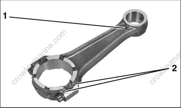
- Oil hole
- Raised dots
002055
Apply Needle Bearing Grease to the wrist pin bearings. Install the bearings in the small end of the connecting rod. Align bearings with Wrist Pin Bearing Tool, P/N 336660.
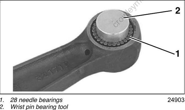
- 28 needle bearings
- Wrist pin bearing tool
24903
Place the two wrist pin thrust washers on the tool with flat side of the washers facing out.
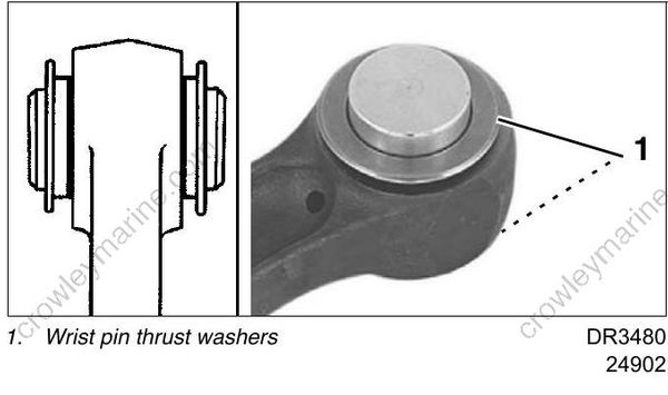
- Wrist pin thrust washers DR3480
24902
Oil the wrist pin bore and wrist pin. Place connecting rod, with bearings, washers, and tool, into the piston with the alignment dots facing the top of the piston.
Install wrist pin through piston and connecting rod, pushing bearing tool out through the piston.
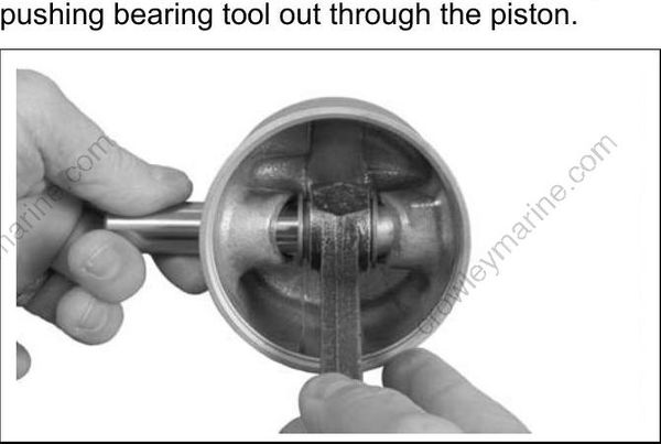
002057
Use Wrist Pin Cone, P/N 318600, and Driver, P/N 318599, to install new wrist pin retaining rings in each wrist pin hole. Gap of retaining ring faces up, away from notch in piston.
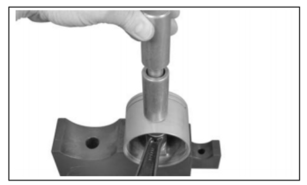
002058

- Gap of retaining ring
- Notch in piston
002050
Installing Pistons
When all pistons and connecting rods are assembled, install piston ring sets. Be sure rings are installed in the cylinder used to test ring end gap. Refer to POWERHEAD INSPECTION on p. 205.
IMPORTANT: Be sure gap of ring fits squarely around dowel pin.
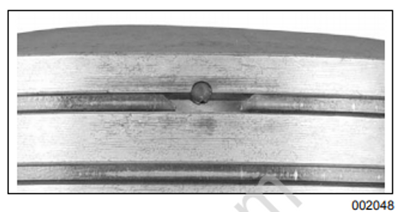
002048
Before continuing, make sure that all Gel-Seal II has been removed from the cylinder block and crankcase mating flanges. If traces of hardened Gel-Seal II are left, main bearings could be misaligned. Refer to CYLIN- DER BLOCK CLEANING on p. 204.
Coat pistons, rings, cylinder walls, and an appropriate ring compressor with outboard lubricant.
Center connecting rod in piston and locate piston rings on dowel pins. Place appropriate ring com pressor on piston.
Slide piston and rod assembly into the correct cylinder, as marked during disassembly. Guide connecting rod through cylinder block to avoid scratching cylinder wall.
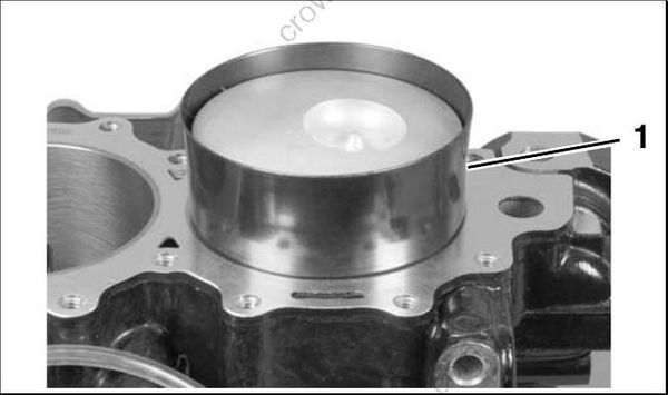
- Ring compressor 002059
Repeat steps for each piston.
Cylinder Head Installation
Install a new thermostat seal in cylinder head with side marked “TO CYL HEAD” facing toward thermostat.
Refer to THERMOSTAT SERVICING on p. 186 before installing cylinder head.
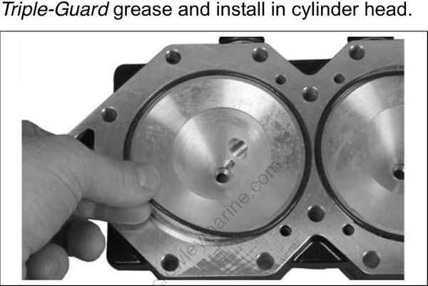
Lightly lubricate new cylinder head O-rings with Triple-Guard grease and install in cylinder head.
002061
Apply soapy water to water dam and insert into block.

- Water dam 002062
002062
Apply a 1/16 in. (2 mm) bead of RTV Adhesive around each water passage on the block and cylinder head as shown.
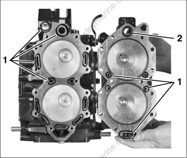
- RTV sealant
- Thermostat seal
002272
Install cylinder head with the thermostat toward the top. Place ignition coil brackets as shown below.
Apply outboard lubricant to screw threads and install the cylinder head screws. DO NOT use any sealant or locking compound on threads.
Following sequence stamped on cylinder head, tighten all screws in stages to a torque of 168 to 192 in. lbs. (19 to 21.7 N·m).

2-Cylinder Models
- Cylinder head screws
- Ignition coil bracket
007850
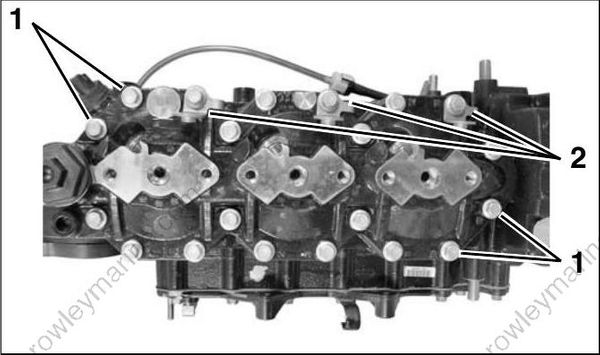
3-Cylinder Models
- Cylinder head screws
- Ignition coil bracket
008192
Crankshaft and Connecting Rod Installation
Apply Gasket Sealing Compound to lower oil seal groove in cylinder block. DO NOT put any sealer in upper seal groove.
Check that main bearing alignment dowel pins are seated in the block.

- Gasket Sealing Compound
- Dowel pins
- No sealer here
002262
Push all pistons to the top of cylinders. Remove numbered connecting rod caps.
Gently lower crankshaft into place.
• Align tab on lower bearing seal housing with hole in crankcase.
• Align upper oil seal in groove.
• Locate each main bearing on its dowel pin. A mark placed on the bearing race opposite the dowel pin hole will help in the alignment process.
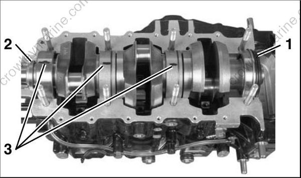
- Lower seal housing
- Upper oil seal
- Alignment marks
002070
Lubricate each crankpin and bearing assembly with outboard lubricant. Slowly pull connecting rod up to crankshaft and install bearing halves.
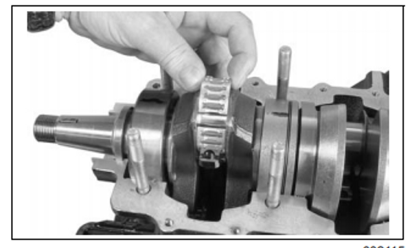
002115
Lubricate rod cap screw threads and under screw head mating surface with outboard lubricant. Align dot on rod cap with dot on the connecting rod. Install rod cap screws finger tight (NO MORE than 6 in. lbs. (1 N·m) maximum).
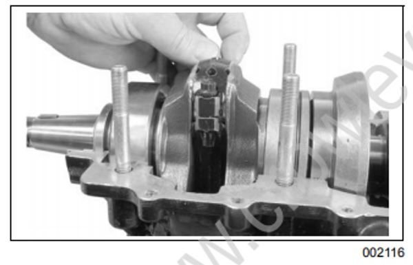
002116
IMPORTANT: Be sure alignment dot on rod cap matches dot on rod and that both dots face flywheel.
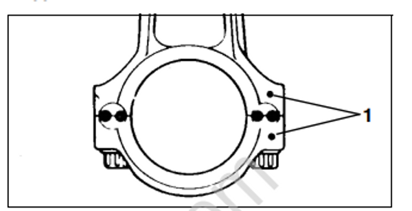
- Alignment dots 53628
Tightening rod cap screws without Alignment Fixture, P/N 396749, or using an incorrect procedure could cause permanent damage to the connecting rod and crankshaft. To maintain accurate torque values, keep torque wrench extension length to a minimum
Install Rod Cap Alignment Fixture, P/N 396749, before tightening rod cap screws. Align the flat marked “SET” on the rod engagement stop with the arrow on the frame. Position stop at the center setting (one line showing). Rotate adjustment knob 180° to lock in position.
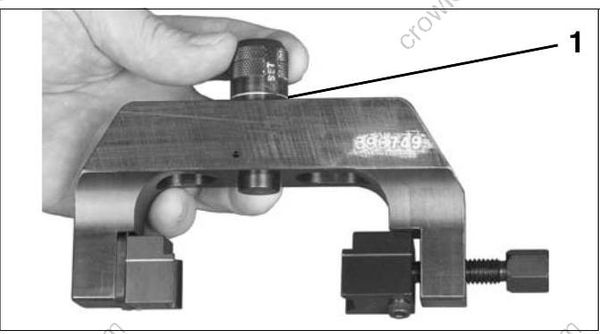
- Center position, one line showing 002484
Secure restraining jaw “C” and forcing jaw “D” to frame.
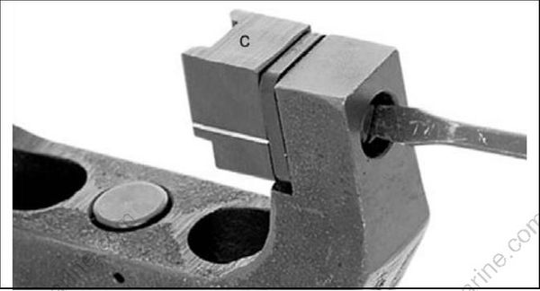
Restraining Jaw “C” 21591
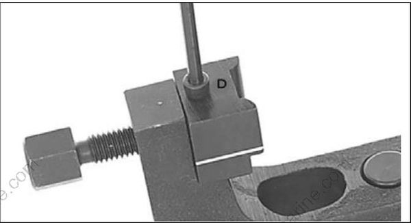
Forcing Jaw “D” 21594
Apply a light coat of outboard lubricant to the corners of the connecting rod and rod cap. Place frame on connecting rod using the following procedure.
• Place frame onto the connecting rod so the contact area of the jaw is centered on the side of the rod.
• Tighten forcing screw until jaws contact connecting rod.
• Slide frame down until adjustment stop contacts the rod cap. The groove lines on the jaws must be centered on the rod/crankpin diameter.
• Tighten the forcing screw to a torque of 14 to 16 in. lbs. (1.6 to 1.8 N·m).

- Contact area of jaw
- Forcing screw
- Adjustment stop
- Groove line
002071
IMPORTANT: Make sure that frame is squarely in position and that rod and cap are aligned. Loosen both rod cap screws one-quarter turn.
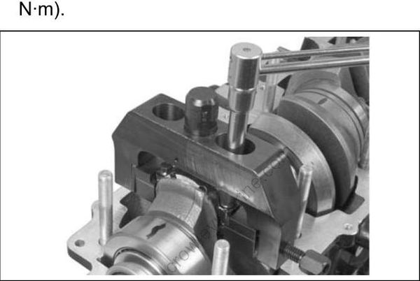
Use Torquing Socket, P/N 331638, to tighten rod cap screws in three stages:
• Apply first torque of 40 to 60 in. lbs. (5 to 7 N·m) to both rod cap screws.
• Tighten screws to a torque of 14 to 16 ft. lbs. (19 to 21.7 N·m).
• Apply final torque of 30 to 32 ft. lbs. (41 to 43 N·m).
002072
IMPORTANT: If a new screw is used, it must be installed as above. Then, it must be removed, re lubricated, and installed again.
Loosen forcing screw and remove the frame.
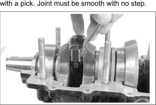
Test at least three corners of the rod and cap joint with a pick. Joint must be smooth with no step.
002117
Crankcase Assembly
Make sure crankshaft is still seated on dowel pins before assembling crankcase.
Thoroughly clean and degrease the mating flanges of the crankcase and cylinder block with a non-petroleum based solvent, such as isopropyl alcohol or acetone, and let air dry.
IMPORTANT: DO NOT allow solvent to get on internal components. Clean only the mating flanges.
Apply Gasket Sealing Compound to lower oil seal groove in crankcase. DO NOT put any sealer in upper seal groove.
Use a small brush with a tapping motion to apply a thin, even coat of Gel-Seal II sealant to the crank case mating flange. The sealer must not come within 1/4 in. (6.4 mm) of bearings.
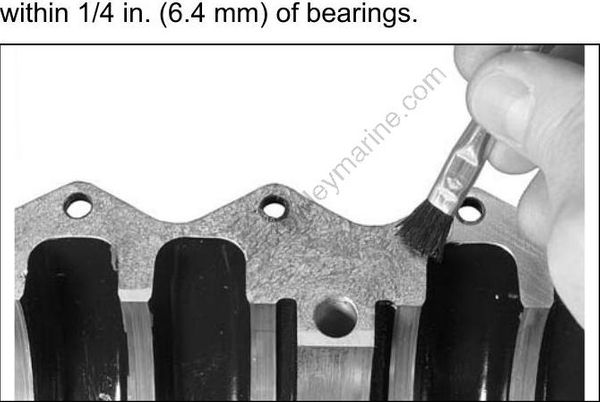
TYPICAL 003874
IMPORTANT: Gel-Seal II has a shelf life of at least one year when stored at room temperature. Test the Gel-Seal II or replace it if the age of the tube cannot be determined. Using old Gel-Seal II could cause crankcase air leaks.
IMPORTANT: The use of Locquic Primer is NOT recommended. If primer is used, crankcase halves must be assembled and tightened within ten minutes after the Gel-Seal II has been applied. Lower the crankcase into place. Make sure that upper oil seal and lower seal housing are seated in grooves.
Apply outboard lubricant to the main bearing studs. Install nuts and washers finger tight, no more than 60 in. lbs. (7 N·m).
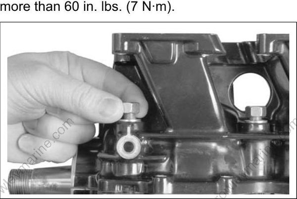
002271
When the crankcase is seated, install and firmly seat the crankcase taper pin.
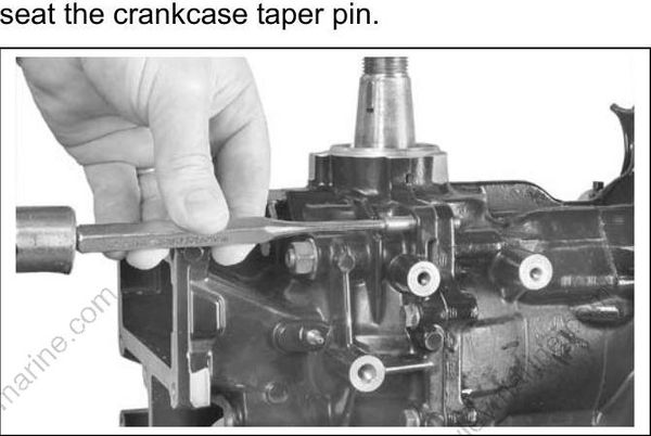
002260
Tighten main bearing nuts in stages to a final torque of:
• 26 to 30 ft. lbs. (35 to 41 N·m)
Start in the center and work outward in a spiral pattern.
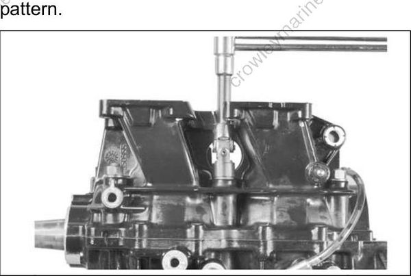
002254
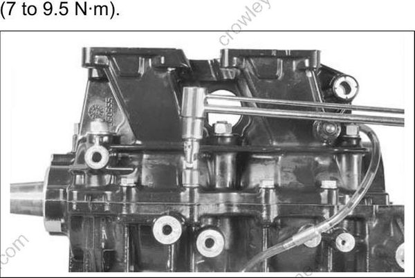
Apply Nut Lock to crankcase flange screws. Install screws and tighten to a torque of 60 to 84 in. lbs.
(7 to 9.5 N·m).
002259
Test that the crankshaft spins freely without binding.
IMPORTANT: After powerhead has been assembled, allow at least two hours for Gel-Seal II to cure before running outboard.
Apply Gasket Sealing Compound to both sides of a new water cover gasket. Place gasket and cover on cylinder block.
Apply Nut Lock to cover screws. Position J clamps as shown. Tighten all screws to a torque of 60 to 84 in. lbs. (7 to 9.5 N·m).
Note: 3-Cylinder models include a double-ended stud and use a lock washer under the J-clamp.
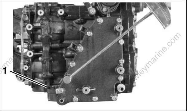
2-Cylinder models
- J-clamp
002242r
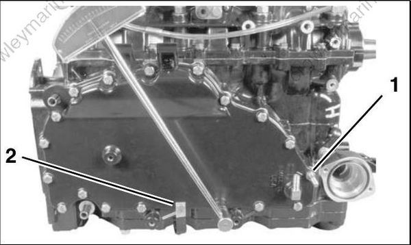
3-Cylinder models
- Double-ended stud
- J-clamp
002122
Shift Linkage Installation
Place the spring, guide, and ball of the shift detent assembly into the crankcase. Lubricate with Triple-Guard grease.
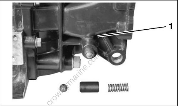
- Shift detent assembly 002135
Lubricate shift linkage bosses at the base of the crankcase with Triple-Guard grease. Insert bushings into bosses.
Apply Triple-Guard grease to the shaft and detent of the shift lever assembly. Guide shaft through bushings in crankcase.
Install cotter pin and washer on the shaft (2-cylin der models).
Install shift rod lever and tighten retaining screw to a torque of 60 to 84 in. lbs. (7 to 9.5 N·m).

- Shift lever and shaft
- Bushing
- Cotter pin and washer
- Shift rod lever screw
002246
Apply Triple-Guard grease to shoulder of shift arm screw and Nut Lock_to threads. Install arm, screw, and washer and tighten screw to a torque of 120 to 144 in. lbs. (13.5 to 16 N·m).
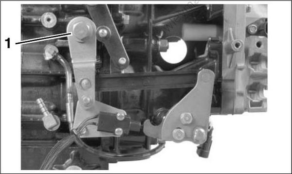
- Shift lever screw 002250
Throttle Linkage Installation
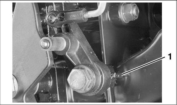
Apply Nut Lock to threads of throttle lever screw. Insert spring into cavity of throttle return lever.
Install lever, screw, and washer on crankcase and hook spring on rib as shown. Tighten screw to a torque of 120 to 144 in. lbs. (13.5 to 16 N·m).

2-Cylinder models
- Throttle lever spring
002255
3-Cylinder models
- Throttle lever spring
002256
Apply Nut Lock to threads of throttle cam screw. Install cam, screw, and washer on cylinder block and tighten screw to a torque of 120 to 144 in. lbs. (13.5 to 16 N·m).
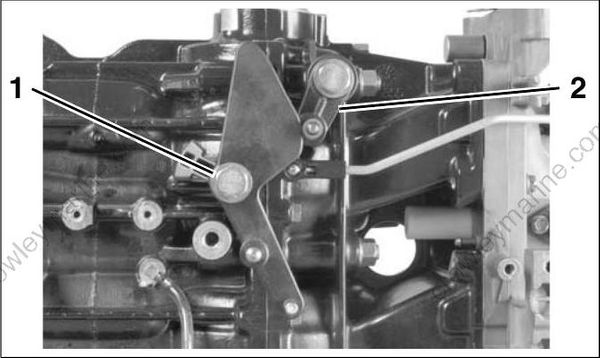
2-Cylinder models
- Throttle lever screw
- Throttle return lever
002245
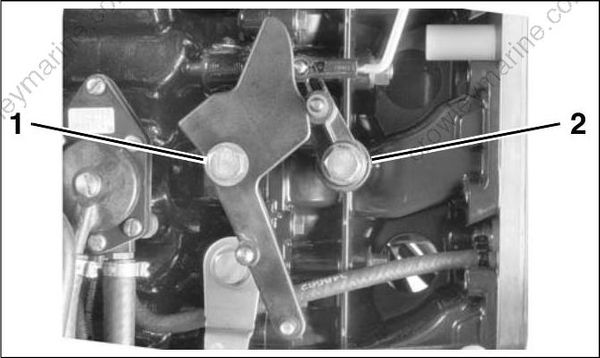
3-Cylinder models
- Throttle lever screw
- Throttle return lever
002257
IMPORTANT: Do not lubricate throttle levers or shoulder screws.
Final Powerhead Assembly
Install the reed plate and throttle body assemblies. Refer to Intake Manifold Service on p. 154.
Install oil recirculating hoses and check valves. Refer to OIL RECIRCULATION DIAGRAMS on p. 162, or POWERHEAD VIEWS on p. 225.
Install thermostat assembly. Refer to THERMOSTAT SERVICING on p. 186. Install pressure valve assembly. Refer to PRESSURE RELIEF VALVE SERVICING on p. 187.
Install shift linkage. Refer to Shift Linkage Installation on p. 216.
Install throttle linkage. Refer to Throttle Linkage Installation on p. 217.
Install fuel injectors and ignition coils. Refer to Fuel Injector Installation on p. 152 and IGNITION COIL SERVICING on p. 116.
IMPORTANT: All injectors must be installed in their original location. Improper injector installation can result in powerhead failure.
Install stator and flywheel. Refer to FLYWHEEL AND STATOR SERVICING on p. 114.
Install electrical harness, then install EMM. Refer to EMM SERVICING on p. 74.
Install fuel pump assemblies, fuel manifolds, and filter. Refer to FUEL COMPONENT SERVICING on p. 146.
Install the oil tank and oil injection hoses. Refer to Oil Tank Assembly on p. 173.
Install the electric starter. Refer to Starter Starter Installation on p. 119.
To prevent fire and explosion hazard, make sure all electrical and ignition wiring is routed and clamped in original positions.