OIL CONTROL SETTINGS
Oil Injection Rate
EMM programming controls the rate of oil injection based on engine RPM. This rate can be adjusted for the type of oil being used, and also for power head break-in. Use Evinrude Diagnostics software to access these features.
The Set Oil Type option controls the injection rate for the oil being used and typical operating conditions.
The TC-W3 oil type setting is the standard setting for all outboards. Set TC-W3 for:
• Operation with all TC-W3 outboard oils including XD30, XD50, or XD100.
• Applications requiring maximum lubrication.
• Extreme applications (commercial or harsh conditions, racing or other high performance operation).
• Use this setting with XD100 outboard oil in extreme applications
The XD100 setting provides an option to run the outboard at a reduced oil injection rate. This set ting REQUIRES the use of Evinrude XD100 out board lubricant and is not recommended for all applications.
IMPORTANT: The XD100 setting is not avail able on all models.
Use the XD100 setting for:
• Conventional use (runabouts, cruisers)
• Moderate applications
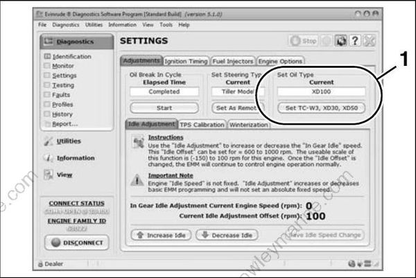
- Oil control setting 008580
Running an Evinrude E-TEC out- board on other grades of oil while set to the XD100 oil ratio will result in increased engine wear and shortened outboard life.
Powerhead oil programming labels are provided to identify EMM oil programming. Install the correct label to alert user to specific oil requirements.
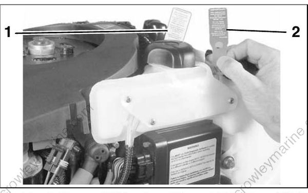
- Evinrude/Johnson XD30 outboard lubricant (TC-W3)
YELLOW label - Evinrude/Johnson XD100 outboard lubricant (Premium)
BLUE label (Installed)
002507
An XD100 Outboard Oil Decal, P/N 352369, is available to label boats equipped with outboards that have been programmed for the reduced oil injection ratio.
This outboard has been programmed for the use of Evinrude ® /Johnson® XD100™ outboard oil ONLY. Failure to use Evinrude ®/Johnson® XD100™ outboard oil may harm engine performance and shorten engine life.
XD100 Outboard Oil Decal 355627
Install decals in a highly visible location, such as one of the following:
• Dashboard/deck of boat, next to key switch
• Deck of boat, next to the remote oil fill
• Deck of boat, next to oil tank assembly
• Oil tank cover
• Cover of oil tank compartment
• Attach to oil tank or oil fill cap
IMPORTANT: Make sure the engine label and boat decals match EMM programming.
Break-In Oiling
IMPORTANT: DO NOT add oil in the fuel tank on Evinrude E-TEC models.
The EMM automatically supplies extra oil to the engine as follows:
• 40 – 90 HP: First two hours above 2000 RPM Follow these steps for outboard set-up:
• Use Evinrude Diagnostics software to make sure the break-in program has been started on a new outboard.
• Use the diagnostics software to start break-in oiling after a powerhead rebuild.
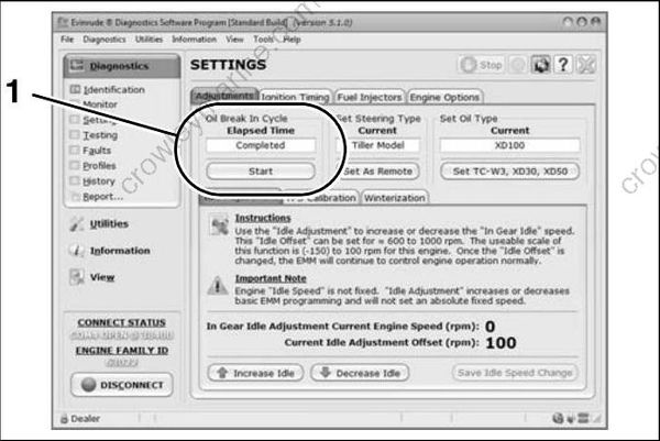
- Break-in oil setting 008580
The operator must monitor the oil tank level to confirm oil consumption. This may require several hours of operation above idle.
Oil Supply Priming
Always use caution while working around machinery with moving parts. The following set-up procedures require running tests that are performed with the out- board’s motor cover removed.
Start the outboard. Use the oil priming function in the software to make sure the system is completely primed.
Use the Prime Oil System button of the Dynamic Test screen to prime the oil pump
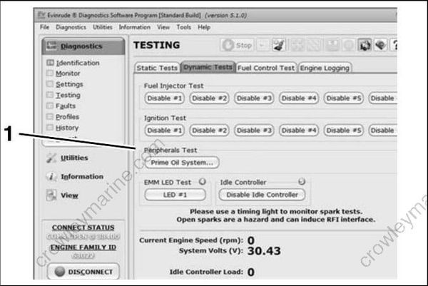
Dynamic Test Screen
- Prime Oil System button
008570A
Observe oil flow through all oil distribution hoses. Air must be purged during the priming procedure.
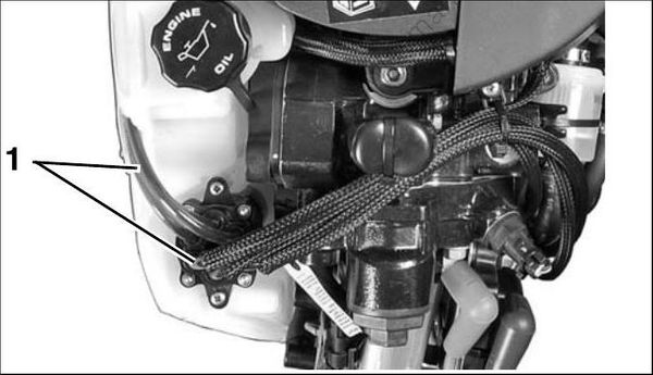
- Oil distribution hoses 007997
Small bubbles are acceptable. Large bubbles must be eliminated through continued priming.
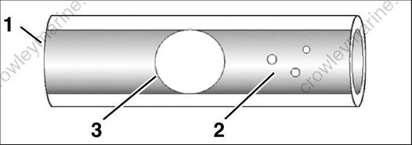
- Oil distribution hose
- Small bubbles
- Large bubbles
004398
Repair any fuel or oil leaks.
The oiling system on these models can also be primed using the Self-Winterizing feature if diagnostics software is not available. Refer to STOR- AGE on p. 49.
OILING SYSTEM TESTS
IMPORTANT: Always perform visual inspections to identify oiling system leaks. Make sure the oil tank is filled and oil supply is not contaminated.
Oil Injection Pump Voltage Tests
IMPORTANT: Do NOT perform static tests using Diagnostic Power Supply Tool, P/N 587005, with internal 9 volt batteries only. This will produce false results. Refer to Communication on p. 67. The EMM controls the pump by providing ground through pin 23 (blue wire) of the J1-B connector and pin B (blue wire) of the oil pump connector.
| Acceptable Oil Injection Pump Test Readings |
|---|
| Key switch ON |
| Control signal |
| Engine running |
Use a digital multimeter calibrated to a scale that reads 12 V (DC) to measure voltage between the oil pump electrical connector and engine ground. Connect negative meter lead to ground.
Use an appropriate test probe to connect positive meter lead to pin B (blue wire) of oil injection pump electrical connector.
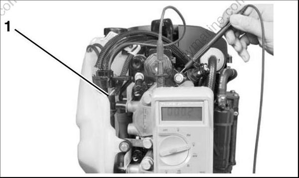
- Oil injection pump electrical connector 008065
Turn the key switch to the ON position. Observe voltage at pin B.
• Voltage at pin B should be approximately 12 V.