GEARCASE REMOVAL AND INSTALLATION
Gearcase Removal
To prevent accidental starting while servicing, twist and remove all spark plug leads.
During service, the outboard may drop unexpectedly. Avoid personal injury; always support the outboard’s weight with a suitable hoist or the tilt support bracket during service.
Remove pin and washer from shift rod lever to release the lower shift rod.
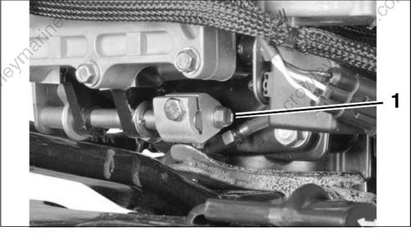
- Shift rod screw
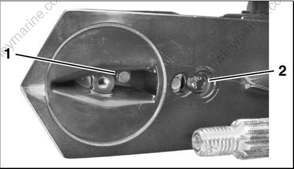
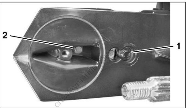
where the index mark on the gearcase aligns with the index number of the adjustable trim tab so the trim tab can be installed in the same position. Remove the trim tab retaining screw and trim tab from the gearcase.
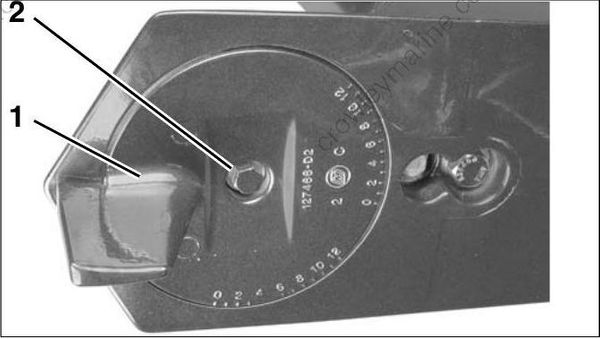
- Trim tab
- Trim tab retaining screw
Remove the 5/16-18 x 1.25 in. screw and washer, and remove 7/16-14 x 3.5 in. screw and washer.
- 5/16-18 x 1.25 in. screw
- 7/16-14 x 3.5 in. screw
Remove the four 3/8-16 x 1.5 in. gearcase retaining screws and washers.
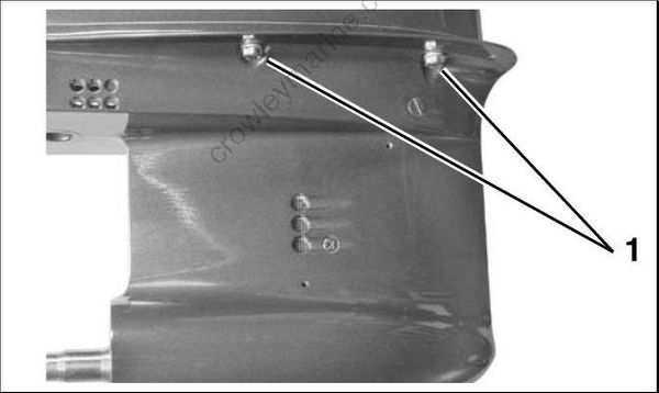
- Gearcase retaining screws
Remove the gearcase assembly from the exhaust housing, being careful not to bend the shift rod.
Gearcase Installation
During service, the outboard may drop unexpectedly. Avoid personal injury; always support the outboard’s weight with a suitable hoist or the tilt support bracket during service.
Before installing gearcase, shift rod adjustment MUST be checked. Refer to SHIFT ROD ADJUSTMENT on p. 296.
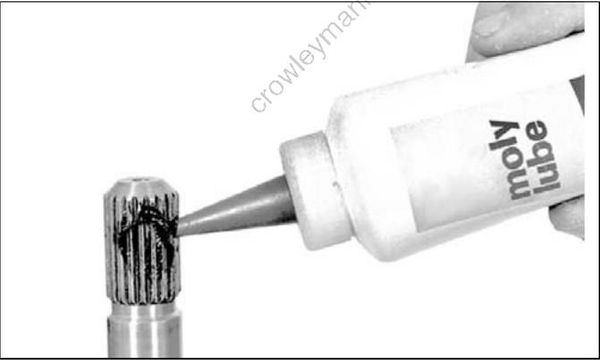
Coat the driveshaft splines with Moly Lube. DO NOT coat top surface of the driveshaft because lubricant may prevent seating of the driveshaft in the crankshaft.
Apply Adhesive 847 to the exhaust housing seal’s outer surface. Place the seal in the gearcase exhaust cavity. Apply Triple-Guard grease to the seal’s inner surfaces.
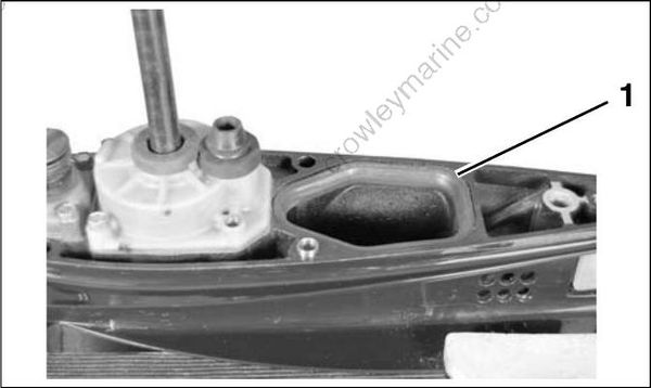
- Exhaust housing seal
Slide the gearcase into place, making sure:
- Driveshaft engages the crankshaft.
- Inner exhaust housing installs correctly.
- Shift rod does not turn and is positioned properly in the shift rod lever below the crankcase.
Apply Triple-Guard grease to threads of the gearcase retaining screws. Tighten the screws to a torque of:
- 3/8 in. screws – 18 to 20 ft. lbs. (24 to 27 N·m)
- 7/16 in. screw – 28 to 30 ft. lbs. (38 to 40 N·m)
- 5/16 in. screw – 10 to 12 ft. lbs. (13.5 to 16 N·m)
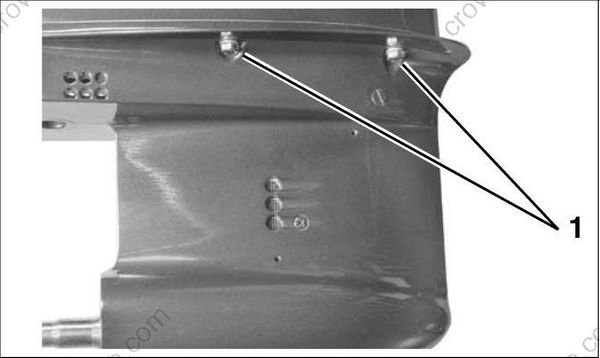
- 3/8 in. screws
- 7/16 in. screw
- 5/16 in screw
Apply Triple-Guard grease to threads of the trim tab screw. Install and align the trim tab with the index marks noted prior to disassembly. Tighten the trim tab screw to a torque of 35 to 40 ft. lbs. (47 to 54 N·m). For adjustment, refer to Trim Tab.
Adjustment on p. 35.
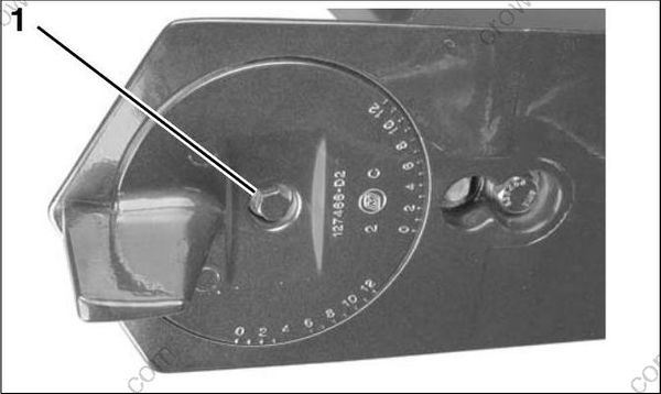
- Trim tab screw
Place the shift rod in the shift rod lever. Install the retaining pin and washer. Tighten pin to a torque of 60 to 84 in. lbs. (7 to 9.5 N·m).
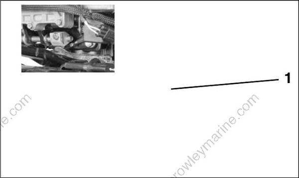
- Shift rod screw
To prevent loss of operator control, check for proper shifting operation and adjust, if necessary.
IMPORTANT: During break-in period of a reassembled gearcase, change the gearcase lubricant between 10 to 20 hours of operation.
WATER PUMP SERVICE
Disassembly
Remove the four impeller housing screws.
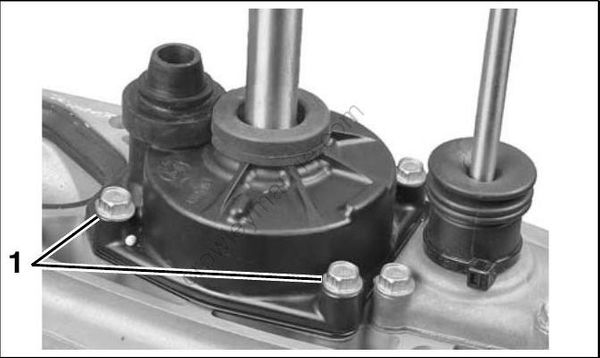
- Impeller housing screws
Slide the water pump off the driveshaft. Remove the impeller key, impeller plate, and gasket. Discard the gasket.
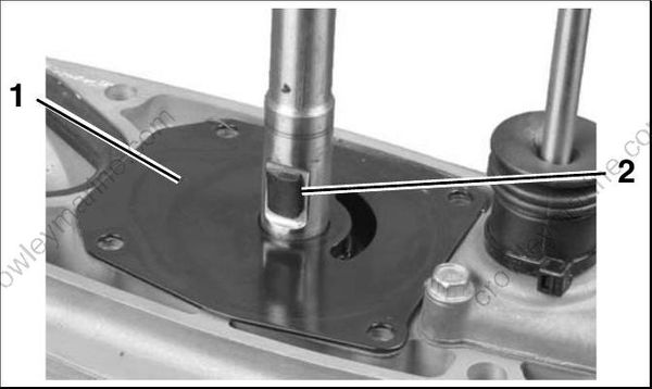
- Impeller plate
- Drive key
Remove all the parts from the housing.
Inspection
Check impeller for overheating, hub separation, and other wear or damage.
Check liner and wear plate for scoring, distortion, and impeller material transfer.
Inspect the housing for cracks or melting.
Make sure gasket surface is clean and smooth.