Step 1: Pre-Disassembly Inspection
Wear safety glasses to avoid personal injury, and set compressed air pressure to less than 25 psi (172 kPa).
IMPORTANT: Clean and inspect all parts during disassembly. Replace any damaged parts, seals, O-rings, and gaskets.
Remove the propeller and mounting hardware.
Drain and inspect oil as described in Gearcase Lubricant on p. 43.
Remove gearcase. Refer to GEARCASE REMOVAL AND INSTALLATION on p. 292.
Remove water pump. Refer to WATER PUMP SERVICE on p. 294
Before disassembling the gearcase, examine the following:
• Gearcase Housing — Check for visible damage to skeg, strut, anti-ventilation plate, bullet, and mating surface. Check seal areas for visible signs of lubricant leakage.
• Propeller Shaft — Check for bent or damaged shaft. Check for twisted splines and damaged threads.
• Shift Rod — Check for misadjusted, bent, or binding rod. A misadjusted shift rod height can cause shift difficulty, loss of boat and outboard control, and gearcase damage.
• Hydrostatic Seal Grooves — Must be in good condition to help prevent propeller ventilation.
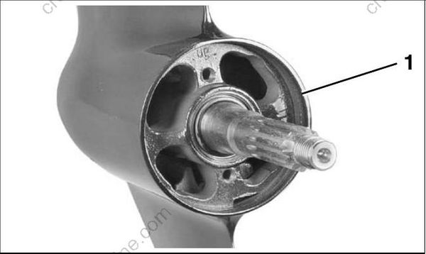
- Hydrostatic seal grooves
• Gearcase Anodes — If anodes have eroded to two-thirds their original size, they must be replaced.
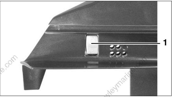
- Gearcase anode
Drive Shaft — Check splines for visible damage, twisting and wear. Severe spline wear indicates the exhaust housing or gearcase has been distorted, possibly by impact damage.
• Water Intake Screens — Check for damage and blockage. If screens cannot be cleaned, they must be replaced. Different screens are available and should not be mixed. Refer to correct model parts manual for listing and description.
Step 2: Propeller Shaft Bearing Housing Removal
Use a 5/16 in. thin wall socket to remove the four screws with O-rings holding the propeller shaft bearing housing.
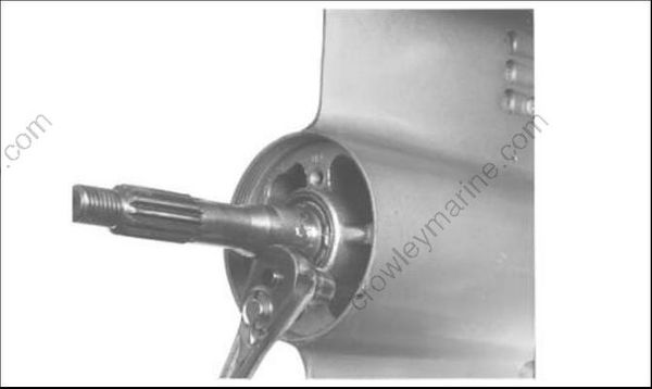
Remove the propeller shaft bearing housing from the gearcase using the following:
- Puller body, screw, and handle from Universal Puller Set, P/N 378103.
- Two 5/16-18 x 8 in. screws, P/N 316982, from Universal Puller Set, P/N 378103.
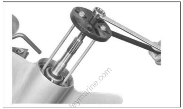
Remove the two retaining rings using Retaining Ring Pliers, P/N 331045.
Retaining rings are under extreme pressure during removal and installation. To prevent personal injury, wear safety glasses and proceed with care to avoid unsnapping the ring from the pliers. After the retaining rings are removed far enough from the gearcase to clear the housing, release the tension on the pliers while retaining ring is still around the propeller shaft.
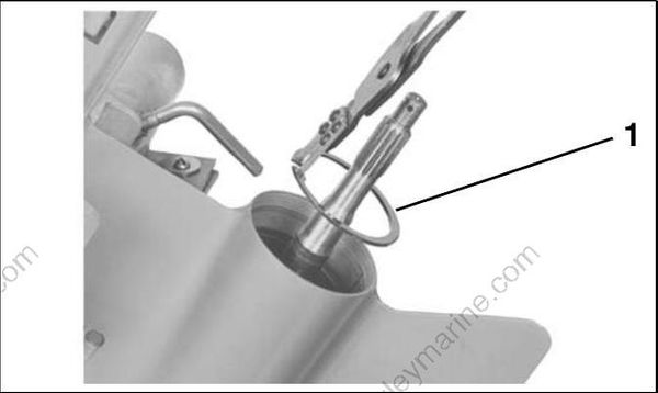
- Retaining ring
Remove the retainer plate from the gearcase.
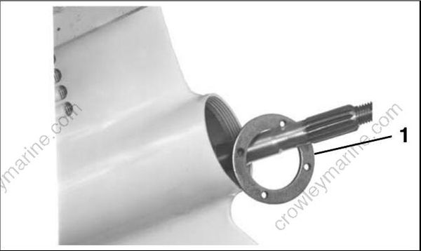
- Retainer plate
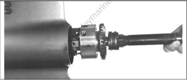
Remove the larger thrust washer, thrust bearing, and reverse gear from the gearcase. Remove the smaller thrust washer located in front of the gear.
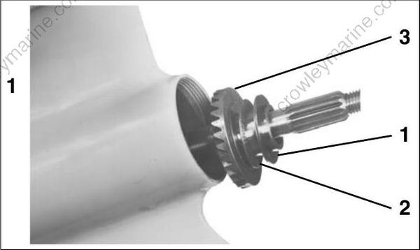
- Larger thrust washer
- Thrust bearing
- Reverse gear
Step 3: Pinion Gear and Driveshaft Removal
Adjust the shift rod to move the clutch dog as far forward as possible. This will help ease removal of the pinion nut.
Use Driveshaft Holding Socket, P/N 334995, and an 11/16 in. open-end wrench to loosen and remove the pinion nut from the bottom of the driveshaft. Pad handle of the wrench to prevent damage to gearcase.
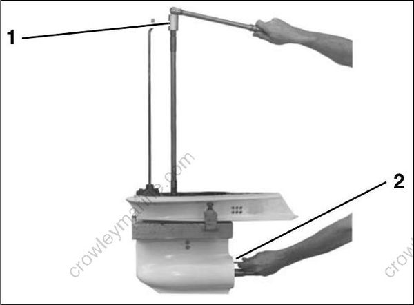
- Holding socket
- 11/16 Wrench
Remove the four driveshaft bearing housing screws.
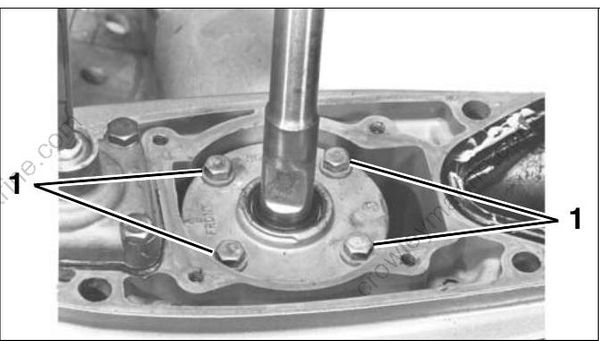
- Driveshaft bearing housing screws
Remove the driveshaft from the gearcase. The bearing housing, shims, thrust bearing, and thrust washer will come out with the driveshaft.
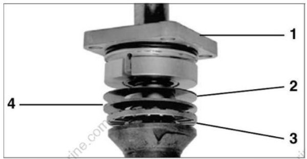
- Bearing housing
- Shims
- Thrust bearing
- Thrust washer
If driveshaft cannot be removed, refer to Locked Driveshaft Removal on p. 300.
Remove the pinion gear from the gearcase.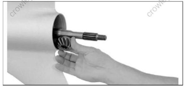
Locked Driveshaft Removal
The driveshaft to pinion taper is a locking taper. If necessary, use Puller, P/N 387206, and Backing Plate, P/N 325867, to break the lock. Install the tools as shown by clamping them around the driveshaft with the tool’s setscrew aligned with the impeller drive key slot. Tighten the setscrew into the slot. Alternately tighten the two vertical screws against the backing plate inserted between the puller and the gearcase until the driveshaft pops loose from the pinion.
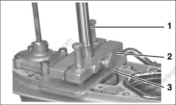
- Drive shaft
- Puller
- Backing plate
Step 4: Shift Housing, Gear and Propeller Shaft Removal
Push down on the shift rod. This will move the detent lever downward to clear the inside of the gearcase when the shaft assembly is pulled out. Unscrew the shift rod from the detent lever. Remove screws, cover, and shift rod from the gearcase.
Discard the cover gasket. Remove and discard the shift rod O-ring from inside of cover.
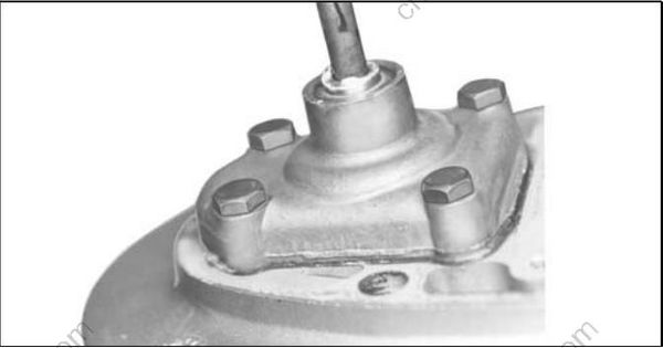
IMPORTANT: Make sure oil fill/drain plug is removed from gearcase.
Remove propeller shaft assembly from gearcase.