DRIVESHAFT SHIMMING
If a new pinion gear is needed, replace gear set before shimming.
Pinion gear backlash is achieved by using shims between the driveshaft bearing housing and the thrust washer. When installing a new thrust bearing or washer, bearing housing, pinion, or driveshaft, it is necessary to properly shim the assembly to restore factory clearance.
Use Driveshaft Shimming Tool, P/N 5005925 (replaces P/N 393185).
Shim gauge bars are precision made and should be handled carefully. The length of each bar is stamped near the part number. This dimension is 0.020 in. (0.508 mm) shorter than the actual shimmed length of the driveshaft.
IMPORTANT: Clean pinion and driveshaft before assembly. Replace any damaged parts.
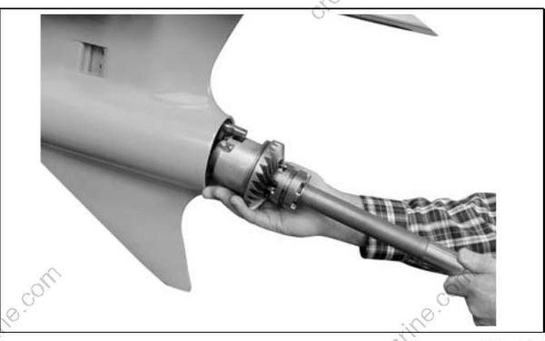
Assemble the driveshaft bearing housing, thrust washer, thrust bearing, and pinion onto the drive shaft. Use Driveshaft Seal Protector, P/N 318674, when installing or removing the bearing housing.
Lightly coat the threads of the pinion nut with out board lubricant and tighten to a torque of 100 to 110 ft. lbs. (136 to 149 N·m).
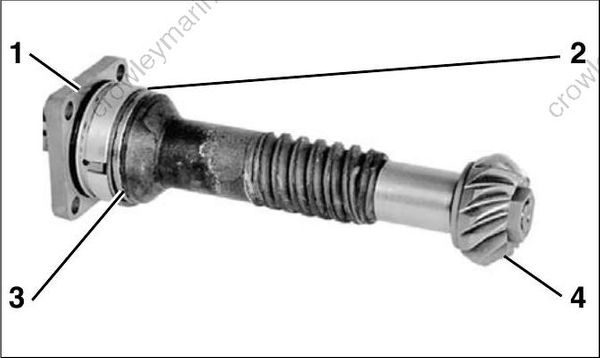
- Driveshaft bearing housing
- Thrust washer
- Thrust bearing
- Pinion
IMPORTANT: The original pinion nut may be used for shimming, but must NOT be used in final assembly.
Select correct collar and shim gauge bar:
- Collar: P/N 341440
- Shim gauge bar: P/N 328367
Slide the collar onto the driveshaft with large end in contact with the bearing housing.
Insert the assembled driveshaft into the tool base and tighten preload screw against the driveshaft until groove on the spring-loaded plunger is flush with end of threads. Tighten locking ring on preload screw.
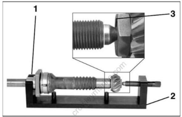
- Collar
- Tool base
- Groove
Rotate the driveshaft several revolutions to seat bearings.
Lay the tool base on its side. Position the shim gauge bar against guide pins of the tool base.
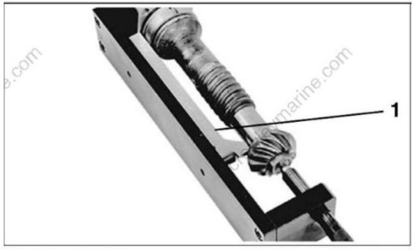
- Shim gauge bar
Check squareness of the bearing housing mounting surface by holding the shim gauge bar against the pinion while rotating just the bearing housing. Use a feeler gauge to measure clearance between the gauge bar and the bearing housing between each pair of screw holes. Replace the bearing housing and repeat check if variance is greater than 0.004 in. (0.101 mm).
Check squareness of the pinion to the driveshaft. Hold the shim gauge bar against the bearing housing (between the screw holes) while rotating just the driveshaft and pinion assembly. Measure clearance between the gauge bar and the pinion at several locations. If variance is greater than 0.002 in. (0.050 mm) replace the pinion or driveshaft, as necessary, and repeat check.
Subtract the average clearance measurement from 0.020 in. (0.508 mm) to determine the correct shim thickness required. Select the fewest number of shims to achieve the correct thickness.
Remove the driveshaft from the tool and add the required shims between the bearing housing and the thrust washer.
IMPORTANT: Use extreme care when removing bearing housing to avoid damaging the seals. Use Driveshaft Seal Protector, P/N 318674.
Check clearance again. The measurement between the gauge bar and pinion should be 0.020 in. (0.508 mm).
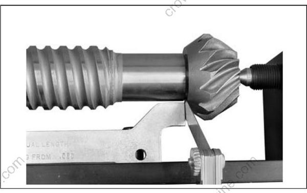
Remove the nut and pinion from the driveshaft. Discard the nut.
GEARCASE ASSEMBLY
Water Intake Screens
Install water intake screens. Tighten screws to a torque of 60 to 84 in. lbs. (7 to 9.5 N·m).
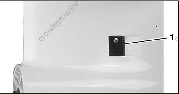
- Water intake screen
Shift Housing, Gear, and Propeller Shaft Installation
Push shifter detent into farthest downward position. Tip the rear of the gearcase slightly downward to assist in the installation of the shaft assembly.
Be sure the thrust bearing and the thrust washer are in the proper position. Insert the shaft assembly fully into the gearcase while aligning shift housing pin with hole in forward end of gearcase housing.