GROUND CIRCUITS
All ground circuits are essential to reliable out board performance. Make sure all ground connections are clean and tight. Refer to wiring diagrams for specific wiring details.
EMM Ground Tests
Disconnect the battery cables at the battery.
Use an ohmmeter to check continuity of ground circuits. Calibrate the ohmmeter on the high ohms scale. Resistance readings for all ground circuits should be 0 W.
- System/power supply grounds: Check continuity between terminal pins 5, 7, and 8 of EMM J2 connector and the main harness ground.
- Injector circuit grounds: Check continuity between terminal pins 14, 20, and 21 of the EMM J1-B connector and the main harness ground.
- Sensor circuit grounds: Check continuity between terminal pins 26 and 27 of the EMM J1-A connector and the appropriate sensor ground connections. Refer to wiring diagrams.
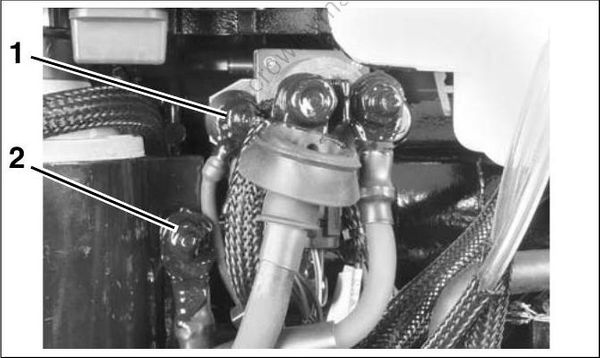
002292
- Main harness ground
- Ground stud (battery)
Additional Ground Tests
Check connections and continuity at the following locations:
- Starter solenoid terminal B and main harness ground.
- Trim and Tilt module ground at main harness ground.
FUSE
The engine harness 12 V (B+) circuit is protected by one automotive style 10 amp minifuse.
The fuse is located on the port side of the power head, in the flywheel cover.
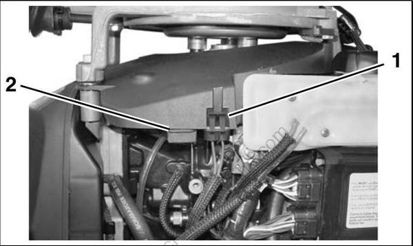
005004
- Fuse
- Spare fuse
IMPORTANT: Repeat failures of fuse could be the result of faulty connections or accessories. The 12 V accessory circuit (purple wire from terminal “A” of key switch) is often used to power accessories.