Anti-Siphon Valve Test
Remove anti-siphon valve from fuel tank. Install adapter fittings and a 36 in. (91.4 cm) length of clear hose to the inlet side (tank end) of valve.
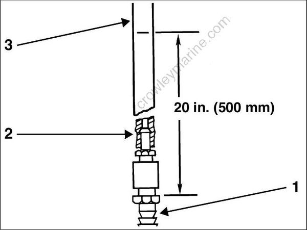
- Anti-siphon valve
- Adapter fitting
- Clear hose
Fill clear hose with water to a height of 20 in. (500 mm). Water must NOT flow through valve. An occasional drip is acceptable. Replace valve if water drips continuously.
Increase height of water to 25 in. (630 mm). Water should flow through valve as water level reaches 25 in. (630 mm). Replace the anti-siphon valve if test results are different.
FUEL COMPONENT SERVICING
Gasoline is extremely flammable and highly explosive under certain conditions. Use caution when working on any part of the fuel system. Protect against hazardous fuel spray. Before starting any fuel system service, carefully relieve fuel system pressure. Refer to Relieving Fuel System Pressure. Always disconnect the battery cables at the battery before servicing the fuel system unless instructed to do otherwise. Always work in a well ventilated area and wipe off any fuel spillage. DO NOT smoke and make certain no open flames or ignition sources exist. After servicing the fuel system check for leaks. Failure to check for fuel leakage could allow a leak to go undetected, resulting in fire or explosion.
Relieving Fuel System Pressure
IMPORTANT: Minimize fuel system pressure before disassembly. Disconnect the fuel supply hose from outboard. Remove propeller and dis connect circulation fuel pump electrical connector. If outboard runs, start and run at IDLE for 5 seconds and STOP outboard. If outboard does NOT run, crank for 10 seconds.
Disconnect the battery cables at the battery.
Wrap a shop towel completely around the pres sure test valve while connecting fitting from Fuel Pressure Gauge, P/N 5007100, to test fitting of fuel pump/vapor separator assembly.
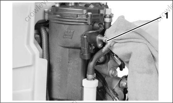
- Test fitting
Insert venting hose of gauge into a suitable container. Slowly open gauge’s venting valve. Clean up any spilled fuel with shop towels.
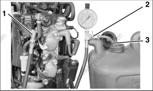
- Test fitting
- Venting valve
- Venting hose
Fuel Filter Service
Removal
Disconnect the battery cables at the battery. Remove filter carefully to prevent spilling con tents. Inspect contents for any presence of water. If water is present, identify the source and correct the problem. Take additional fuel samples and drain fuel tank(s) if necessary.
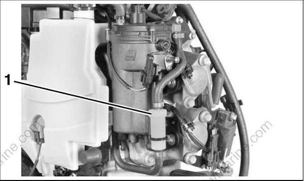
- Fuel filter flange
Installation
Install filter in fuel supply hoses. Flanged part of filter is up. Secure filter with appropriate clamps. Squeeze primer bulb to prime fuel system. Hold pressure on bulb and check for fuel leaks. Connect battery cables. Run outboard and check for fuel leaks.
Fuel Lift Pump Service
The fuel lift pump is serviceable as a complete assembly. Refer to parts catalog for service parts.
Removal
Disconnect the battery cables at the battery. Remove port lower motor cover. Refer to Lower
Cover Removal. Remove the oil tank. Refer to Oil Tank Assembly on p. 157. Use an appropriate tool to remove the push nuts that retain fuel pump to oil tank. Remove the fuel hoses from the fuel pump housing
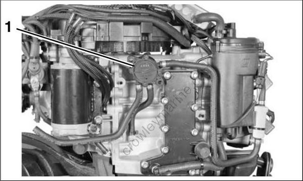
- Fuel pump housing
Remove the fuel lift pump.
Installation
Connect the fuel hoses to the fuel pump. Secure with Oetiker clamps. Place fuel pump in position on the oil tank. Secure the fuel pump with new push nuts, P/N 354365.
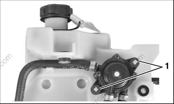
- Push nuts
Be sure fuel hoses are routed in channels on oil tank. Install the oil tank. Refer to Oil Tank Assembly on p. 157. Squeeze primer bulb to prime fuel system. Hold pressure on bulb and check for fuel leaks. Connect battery cables. Run outboard and check for fuel leaks.
Vapor Separator and Fuel Injector Service
Vapor Separator Removal
Relieve fuel system pressure. Refer to Relieving Fuel System Pressure on p. 130. Disconnect the battery cables at the battery. Remove oil tank. Refer to Oil Tank Assembly on p. 157. Disconnect vapor separator and fuel injector electrical connectors. Remove connectors from retainers.
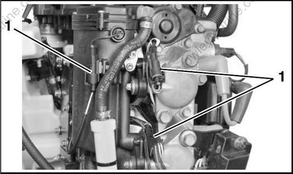
- Electrical connectors
Remove clamps and fuel supply hose, vapor separator vent hose and cooling water hoses.
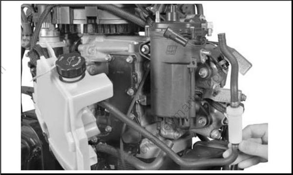
Loosen four injector screws. Remove three vapor separator retaining screws. Remove vapor separator.
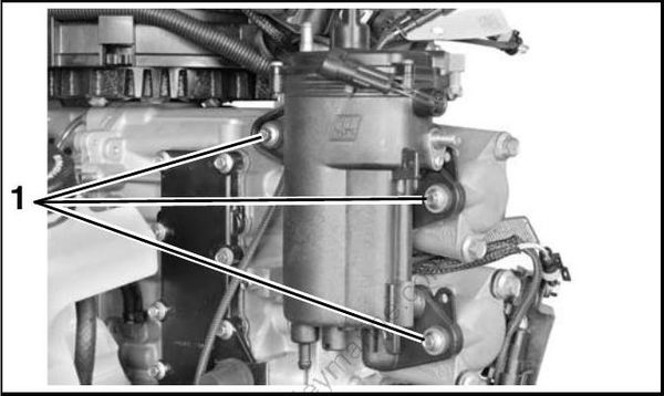
- Retaining screws
Fuel Injector Removal
Mark fuel injectors to show cylinder locations.
Fuel injectors must be installed in the correct cylinder locations. Use Evinrude Diagnostics Software to make sure that EMM programming matches injector positioning. The Injector Coefficients screen displays injector serial numbers for each cylinder.
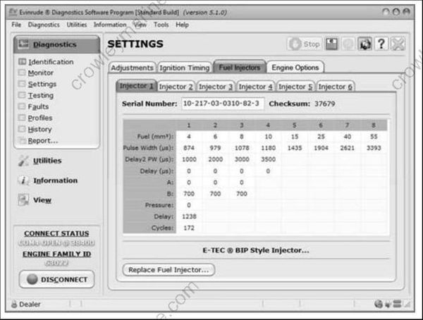
Injector Coefficients Screen
Use caution when handling fuel injectors. Prevent dirt and debris from entering fuel inlet and outlet ports of injectors. Cover the injector nozzle port in cylinder head to prevent contamination of combustion chamber.
Remove injector screws.
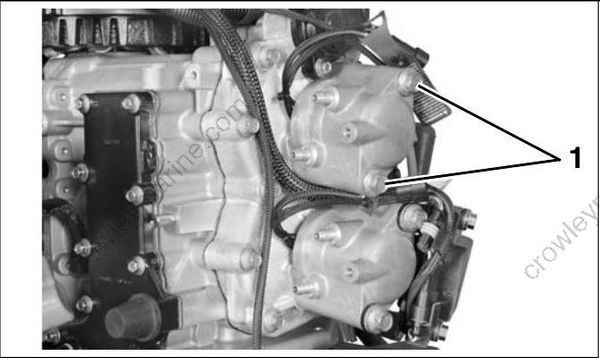
- Injector screws
Remove fuel injector and insulator.
Crush Ring Replacement
Injector crush rings must be replaced if injector is installed in a different head or cylinder location.
Use Injector Puller Kit, P/N 356461, to remove injector from mounting cup. Turn the nut of the fuel injector puller counter– clockwise several turns. Place the fuel injector puller on the fuel injector housing.
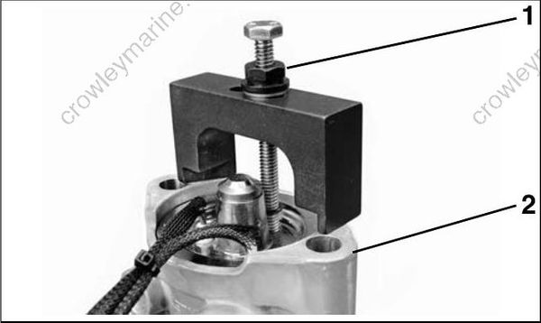
- Puller nut
- Fuel injector housing
Align the angled edges of both sides of the tool base with the edge of the fuel injector housing as shown.
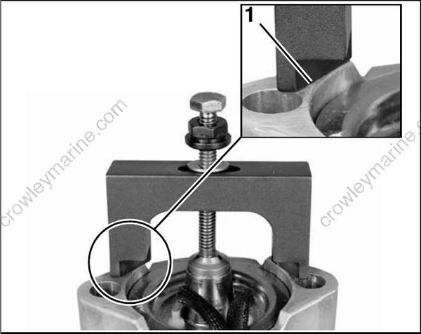
- Angled edge of the tool base
Thread the puller screw into the fuel injector 1/4 20 threaded hole until it seats.
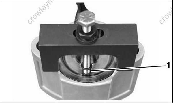
- 1/4-20 threaded hole
Turn puller nut clockwise until it contacts the puller base. Use a 1/2 inch (13 mm) wrench to continue turning the puller nut clockwise. Turn the puller nut until the fuel injector is removed from the fuel injector housing.
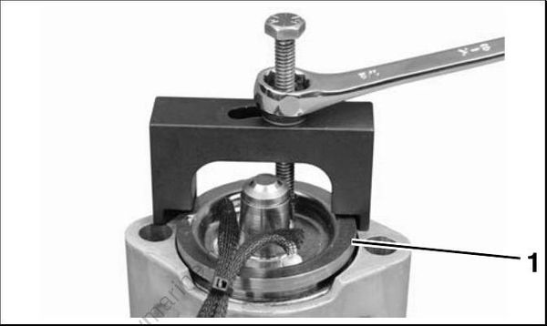
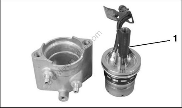
- Fuel injector removed from fuel injector housing
Remove fuel injector puller from injector. Remove crush ring and O-rings from injector. Inspect and clean injector filter. Install new crush ring and O rings. Lubricate O-rings with STP † Oil Treatment.
- Adaptor
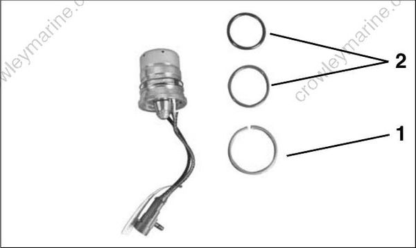
- Crush ring
- O-rings
Install injector into mount housing. Press on injector face until injector seats in mount housing.
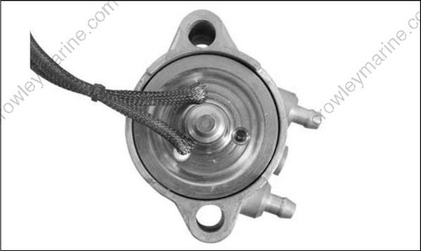
Fuel Injector Installation
All injectors must be installed in the correct cylinder by serial number. Improper injector installation can result in power head failure.
Installation of a replacement injector requires that coefficient data for the new injector is uploaded to the EMM.
Coefficient data for some replacement injectors is supplied on a computer disk shipped with the injector. If a disk is not included with the injector, coefficient data can be downloaded from the Evin-rude/Johnson_ dealer website. Refer to the instructions provided with the injector kit.
Upload Coefficient Files to EMM
IMPORTANT: If using Diagnostic Power Supply Tool, P/N 587005, to supply power to the EMM,
use Accessory Power Cable Kit, P/N 5008092, to connect an external 12 volt battery to the Power Supply Tool.
If the internal batteries of the Power Supply Tool have a low voltage condition the EMM could turn OFF during the coefficient upload, resulting in a failed update. Use the Evinrude Diagnostics software Settings screen to upload the coefficient file to the EMM. Select the Injectors tab. Select the cylinder tab for injector being replaced. Select the cylinder tab for injector being replaced. Select the Replace Injector button.
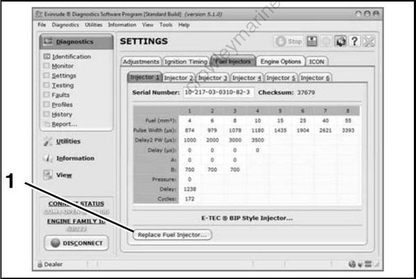
- “Replace Injector” button
Use the drop down menu to navigate to the saved coefficient file location. The coefficient file name must match the serial number of the injector. Select the correct file for the injector. Select the Replace Injector button.
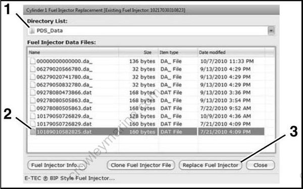
- Navigation menu
- Injector coefficient file
- “Replace Injector” button
After the upload is complete, the program will return to the Cylinder tab. Make sure the serial number displayed on the screen matches the serial number printed on the serial number label of the replacement injector.
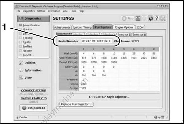
- Serial number
Install Injector
The following items and their mating surfaces must be cleaned prior to reassembly:
- Injector
- Cylinder head
- Adapter
- Screws
- Threaded areas.
All injector components must be clean to ensure correct torque tightening specifications. To prevent fuel leakage, carefully follow these installation instructions.
Lubricate mounting screw threads and under the head of the screw with a light coat of Triple-Guard grease. Install washers (one per screw) on injec tor retaining screws. Install screws and washers through mounting flange of injector. Lower cylinder screws go through the coil mounting bracket.
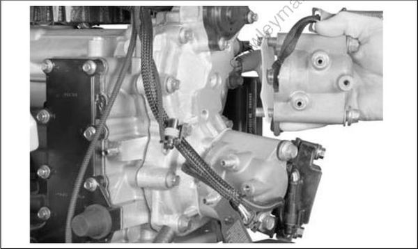
IMPORTANT: Be careful not to pinch any wiring during assembly.
Place injector and insulator in the proper cylinder location. Temporarily install injector screws finger tight.Position fuel injector wiring, vapor separator wiring and electrical connectors as shown.
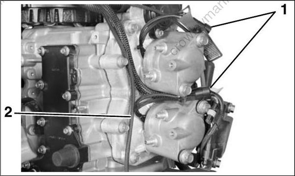
- Fuel injector wiring and connectors
- Vapor separator wiring
IMPORTANT: Fuel injectors MUST be able to rotate slightly during installation of vapor separator.
Vapor Separator Installation
Install new injector seals in vapor separator.
Lightly lubricate seals with a drop of outboard lubricant.
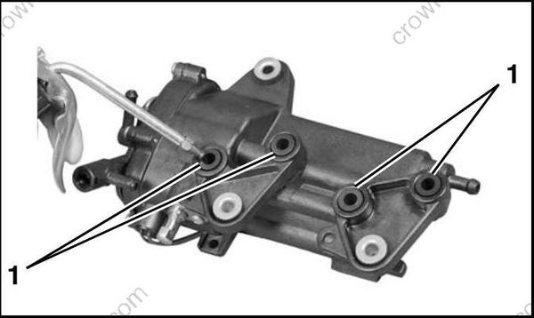
- Injector seals
Install vapor separator assembly onto the four fuel injector fittings.
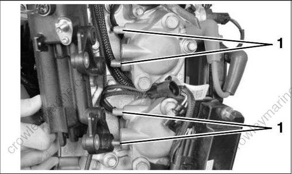
- Fuel injector fittings
Install three vapor separator retaining screws. Tighten two vapor separator to fuel injector mounting screws to a torque of 31 to 48 in. lbs. (3.5 to 5.5 N·m).
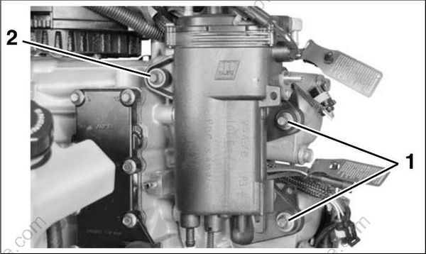
- Vapor separator to fuel injector mounting screws
- Vapor separator to power head mounting screw – Leave LOOSE at this time
IMPORTANT: Fuel injector screws must be tightened before vapor separator to power head mounting screw.
Tighten injector screws in stages, starting with the lower screw.
- First torque is 4.5 ft. lbs. (6 N·m).
- Second torque is 9 ft. lbs. (12.2 N·m).
- Third torque is 14 ft. lbs. (19 N·m).
- Final torque is 22 to 23.5 ft. lbs. (30 to 32 N·m).
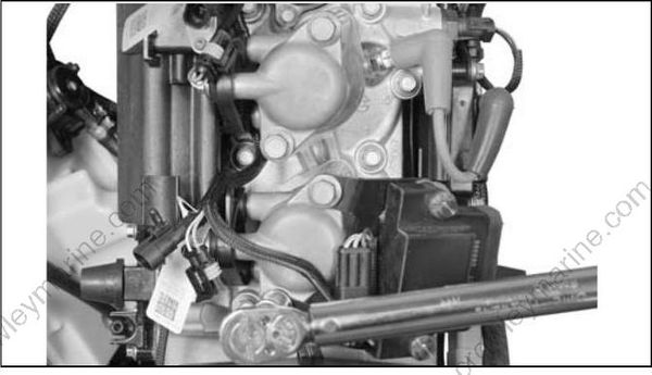
Tighten Screws in Stages
Tighten vapor separator to power head mounting screw to 31 to 48 in. lbs (3.5 to 5.5 N·m). I
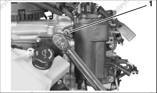
- Vapor separator to power head mounting screw
Install fuel supply hose. Secure with Oetiker clamps. Reinstall vapor separator vent hose and cooling water hoses. Secure with tie straps. Attach fuel filter to vapor separator with tie strap. I
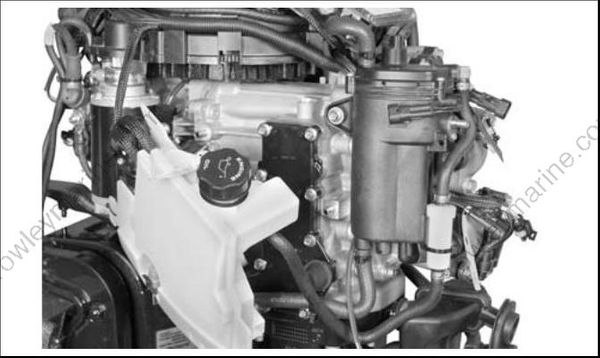
Reinstall protective cap on the pressure test fit ting. Reconnect fuel injector electrical connectors. Reconnect circulation fuel pump electrical connector.
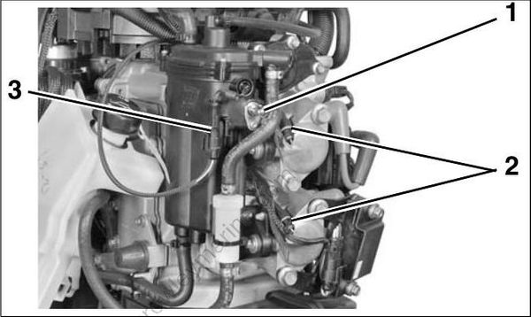
- Protective cap
- Fuel injector electrical connectors
- Circulation fuel pump electrical connector
Reinstall the oil tank. Refer to Oil Tank Assembly on p. 157. Reconnect the battery cables at the battery. Reconnect fuel hose connector to outboard.
**IMPORTANT:**Install injector service data (3.5 in. floppy disk) by using the Injector Replacement Utility of Evinrude Diagnostics software. Check the Injector Coefficients screen to make sure that all injectors are positioned properly
Squeeze primer bulb to prime fuel system. Hold pressure on bulb and observe for fuel leaks. Use static test screen of Evinrude Diagnostics_ software to run fuel pump. Observe for fuel leaks. Run outboard and check for fuel leaks.
IMPORTANT: Pay close attention to fuel vapor separator / fuel injector connection for leaks.
Repair any leaks before returning outboard to service.
Intake Manifold Service
Removal
Disconnect vapor separator vent hose, main bearing vent hose, air temperature sensor, crankshaft position sensor, and throttle position sensor. Use Ball Socket Remover Tool, P/N 342226, to remove throttle link arm. Remove throttle body screws and throttle body assembly.
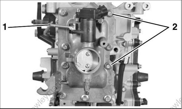
- Link arm
- Throttle body screws
Remove gasket from throttle body. Remove screws and reed plate assembly from the crankcase.
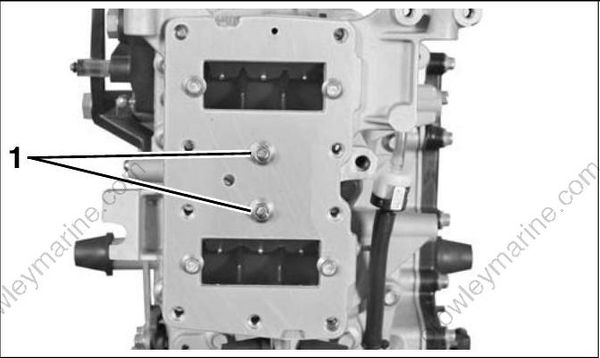
- Screws
Disassembly
All reed plate assembly and reed valve assemblies must be cleaned prior to reassembly. DO NOT use strong carburetor cleaner or the hot soaking tank method for cleaning. Remove the reed valve retainer screws and remove the assembly.
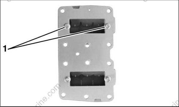
- Screws
Use caution to prevent damaging reed valve assemblies.
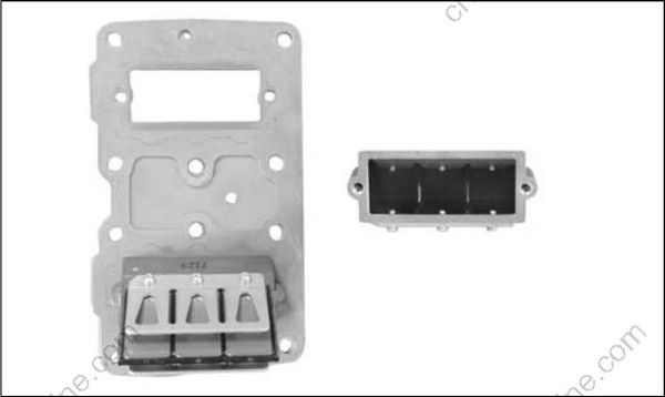
DO NOT disassemble reed valve assemblies. Damaged reed plates are not ser- vice able and are replaced as an assembly.
Inspection
Inspect the leaf plate assemblies for damage or contamination:
- Leaf plates must not be distorted.
- Leaf valve must not be cracked or chipped.
- Leaf plate stops must not be distorted or loose.
- Leaf plate assemblies must be clean.
Inspect the intake manifold. All gasket surfaces must be cleaned, smooth, and free of nicks. Use a machinist’s straight-edge and a feeler gauge to check flatness in all directions. Surface must be flat, ± 0.004 in. (0.10 mm).
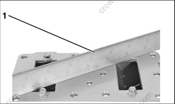
- Straight-edge
Assembly
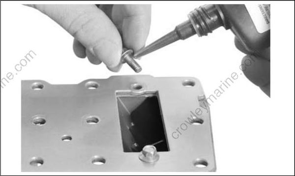
Remove old adhesive from reed valve retaining screws. Install gasket on reed plate assembly. DO NOT use sealer on the gasket.
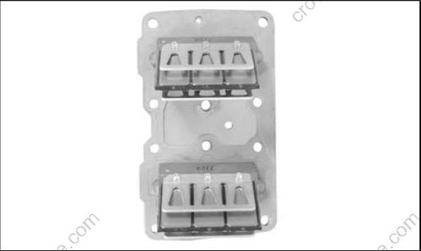
Prime screw threads with Locquic Primer and let dry. Apply Ultra Lock to threads. Position reed
valve on reed plate and install screws. Tighten screws to a torque of 35 to 60 in. lbs. (4.0 to 6.8 N·m).
Installation
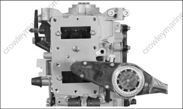
Place reed plate assembly on cylinder/crankcase. Apply Nut Lock to reed plate screws. Install and
tighten screws to a torque of 84 to 106 in. lbs. (9.5 to 12 N·m).
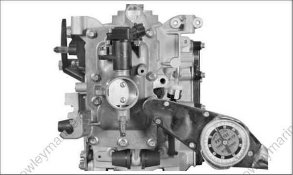
Place gasket on throttle body. Install throttle body on reed plate and install new screws.
IMPORTANT: If old screws must be re-used, make sure all previous thread locking material is
removed and apply Nut Lock to threads.
Tighten the center screws first and expand out ward. Tighten in stages to a final torque of 84 to 106 in. lbs. (9.5 to 12 N·m).
Install vapor separator vent hose and main bearing vent hose. Secure with tie straps. Install crankshaft position sensor, and throttle position sensor electrical connectors. Connect throttle linkage.
IMPORTANT: DO NOT lubricate throttle link ages.
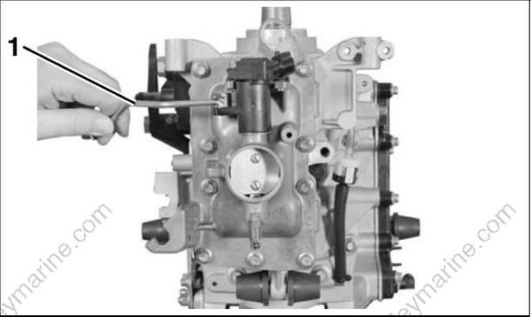
- Throttle linkage
Refer to TPS Calibration on p. 106.