

1) Inspection of Top Cowl
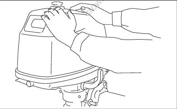
Push top cowl using both hands to check for looseness and seal when cowl latched.
2) Fuel System
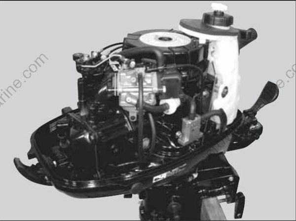
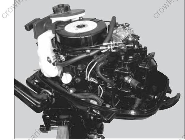
Check piping
Remove top cowl and check each section for fuel leak, dirt, deterioration and damages. Clean or replace parts if necessary.
3) Inspection of Fuel Tank
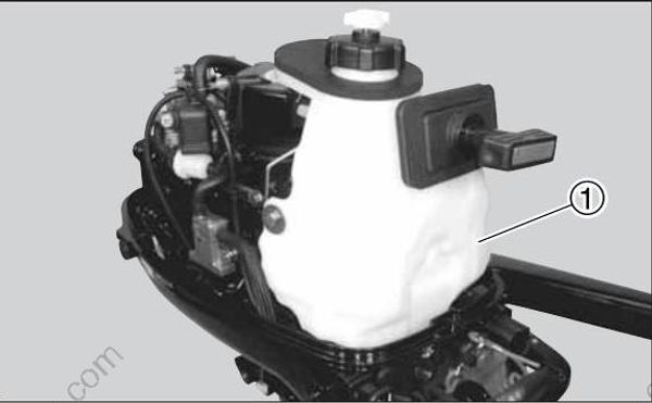
< For Dual Tank Model >
Remove dirt and water from fuel tank (1) if any.
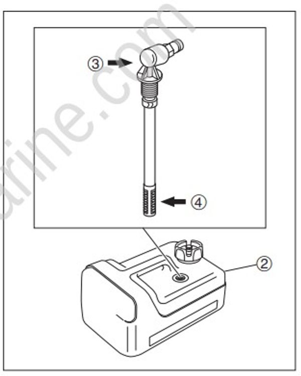
(3) Fuel Pickup Elbow
(4) Filter
< For separate Fuel Tank model >
Turn fuel pick up elbow (3) of fuel tank (2) counterclockwise to remove the part, and clean the filter (4). Remove dirt and water from fuel tank (2) if any.
4) Inspection of Fuel Filter
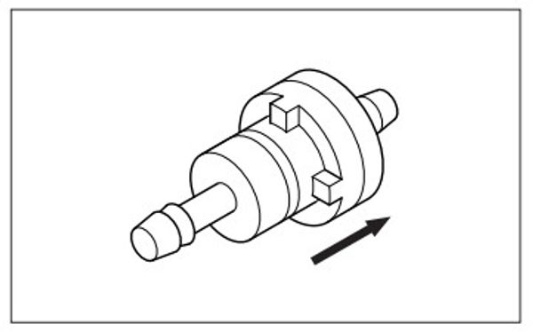
Check fuel filter for dirt, build up of fuel residue, and fuel filter for invasion of foreign matter and cracks. Replace fuel filter if necessary.
· Do not spill fuel when removing fuel filter.
· Be careful to installation direction. Fuel flows to the direction of the arrow mark.
5) Replacement of Engine Oil
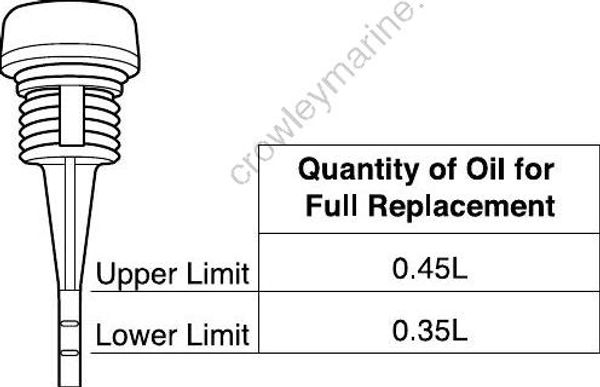
- Oil Level
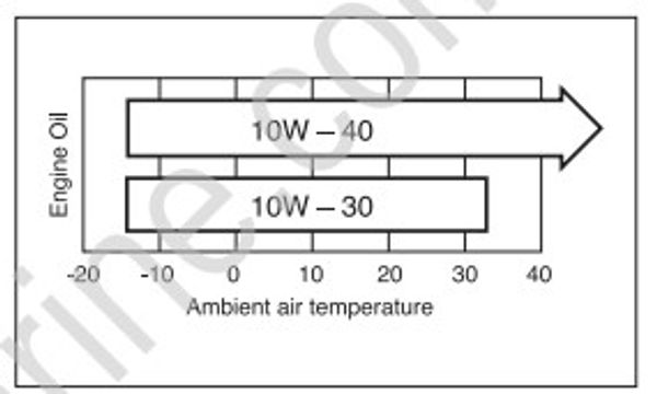
2. Oil Specification
Engine Oil :
4 Stroke Engine Oil
API: SE, SF, SG, SH, SJ, SL, SM
SAE: 10W-30, 10W-40
NMMA : FC-W Certified 10W-30/40
Quantity of Engine Oil :
0.45L (0.5qt)
Use oil with viscosity that is suited to ambient air temperature of the operating region.
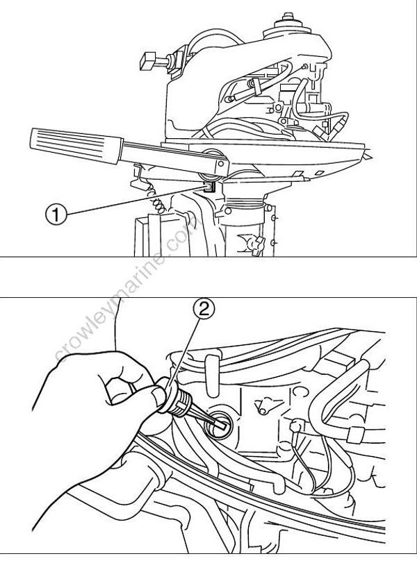
- Engine Oil Replacement Procedure
1. Stop engine and wait till it cools down.
Position outboard motor so that engine oil can be drained from drain bolt (1) easily.
2. Remove oil level gauge (2).
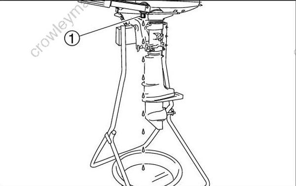
3. Place drain oil pan below drain bolt (1).
4. Remove drain bolt (1) to drain oil.
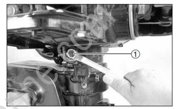
5. Tighten drain bolt (1).
6. Pour new oil into oil inlet until oil level reaches upper limit mark of oil level gauge.
7. Start and run engine for 5 minutes to warm up.
8. Stop engine and check oil level and for oil leaks after 5 minutes.
6) Inspection of Gear Oil Quantity
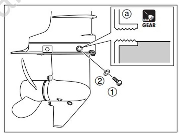
2 Washer Do not reuse.
- Tilt down outboard motor to make it vertical.
- Remove upper oil plug (1) and check level of gear oil in the gear case.
Spill of some oil from plug hole (a) as plug is removed indicates that gear case is filled with specified quantity of gear oil.
- Add recommended gear oil to specified level if it is low.
Gear Oil :
Hypoid Gear Oil
API : GL-5
SAE : 80W-90, 90
If the oil is low, add through lower oil plug hole.
- Attach upper oil plug (1).
7) Inspection of Water Pump
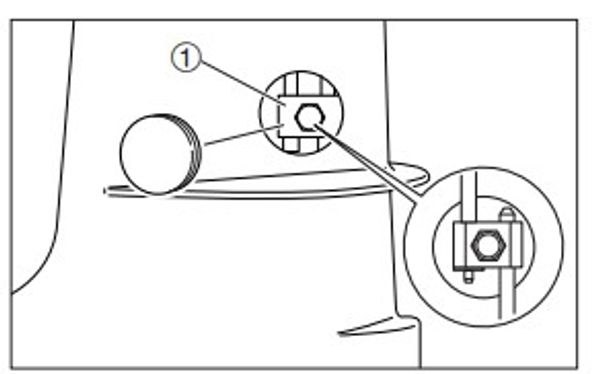
Loosen shift rod joint bolt and separate shift rod pieces.
(Disconnect shift rod at lower side of shift rod joint (1).)
Be careful not to drop shift rod joint and bolt when they are removed.
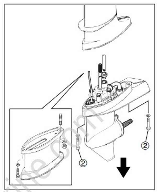
- Remove lower unit installation bolts (2), and pull lower unit ass'y downward to remove.
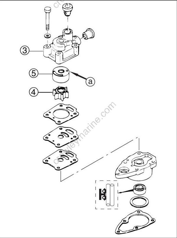
Remove pump case (Upper) (3).
Remove impeller (4) and check it.
Check upper pump case for deformation. Replace if necessary.
Check impeller (4) and pump case liner 5 for cracks and wear. Replace if necessary.
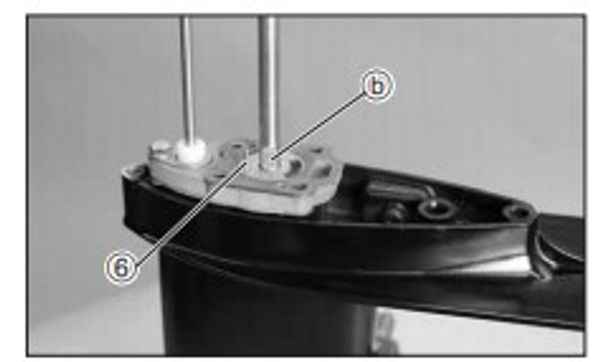
- Check pin (6) and drive shaft groove (b) for wear. Replace if necessary.
- Reinstall the part. For details, refer to Chapter 6.
8) Replacement of Gear Oil
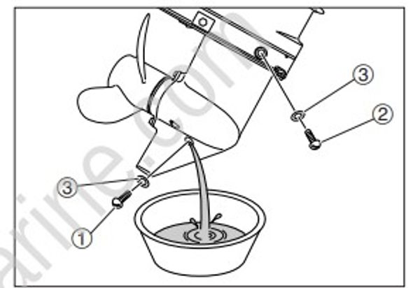
(3) Gasket Do not reuse
Tilt outboard motor a little as shown.
Place drain oil pan below oil plug (1), remove lower oil plug (1) and then upper oil plug (2) to drain oil.
Remove lower oil plug first when draining.
- Check gear oil for presence of metal particles, change of color (abnormal if clouded), and viscosity.
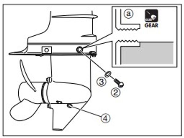
(3) Gasket Do not reuse
- Fill with gear oil (from oil tube or pump) through lower plug hole (4) until gear oil starts to spill from upper oil plug hole (a) without air bubbles.
Gear Oil :
Hypoid Gear Oil
API : GL-5 SAE : 80W-90, 90
Quantity of Gear Oil : 195 cm3 (6.6fl.oz)
Use lower plug hole when filling with gear oil. Upper hole cannot be used because doing so will not allow air to escape from gear case.
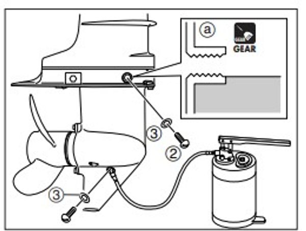
(3) Gasket Do not reuse
- Attach new gasket and upper oil plug (2), and then new gasket and lower oil plug (1) immediately.
When fully filled with oil, attach upper oil plug first.
9) Inspection of Gear Case (for leakage)
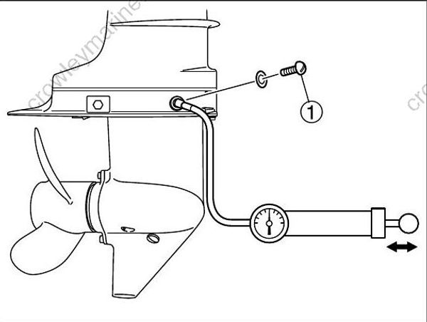
Drain gear oil.
Remove upper oil plug (1) and connect a commercially available leakage tester to this hole.
- Apply specified pressure to gear base, and check if the pressure is maintained without further compression for 10 seconds.
Specified Gear Case Maintained Pressure : 0.049 MPa (7 psi) [0.5 kgf/cm2]
· Rotating propeller shaft while maintaining pressure and testing with gear oil drained make it easy to find leakage due to wear of oil seal lip.
· Depressurize gear case and cover oil plug area with a piece of rag before disconnecting leakage tester.
Do not apply pressure to gear case over specified value.
Doing so can cause damage to oil seal.
- If the specified pressure cannot be maintained, check oil seals of drive shaft and propeller shaft and O ring of shift shaft, and propeller shaft housing and water pump case lower for damages.
10) Inspection of Spark Plugs
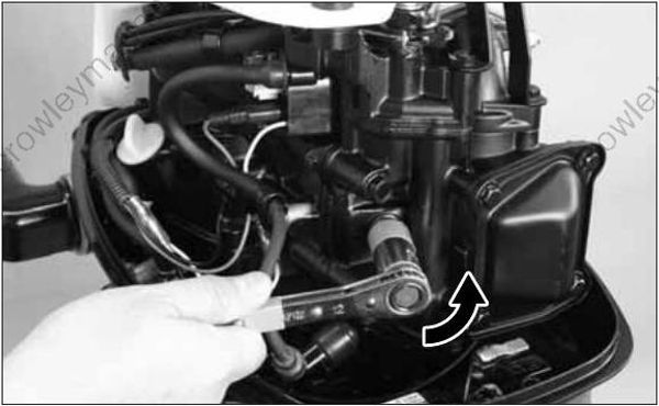
- Remove plug caps and then spark plugs.
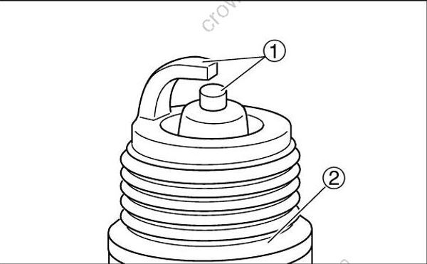
- Use spark plug cleaner or wire brush to clean spark plug electrodes (1). Replace if necessary.
- Check electrodes (1) for corrosion or excessive build up of carbon, and washer (2) for damage. Replace if necessary.
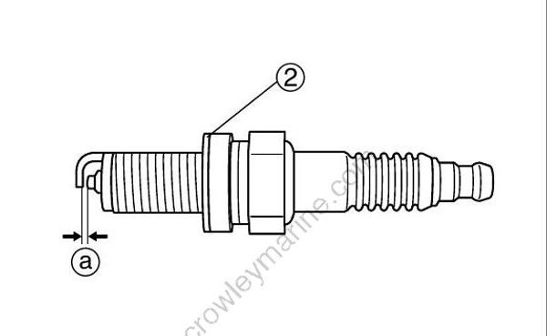
- Check spark plug gap (a). Replace if it is over specified value. Adjust gap if it is out of specified range.
Spark Plug Gap (a) : Standard value 0.8 - 0.9mm (0.031 - 0.035in)
Functional Limit : 1.2mm (0.047in)
Specified Spark Plug : DCPR6E [NGK]
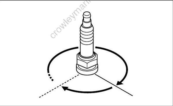
- Install spark plug, fully hand-tighten, and then use plug wrench to tighten to specified torque.
Spark Plugs : 18 N · m (13 lb · ft) [1.8 kgf · m]
11) Inspection of Compression Pressure
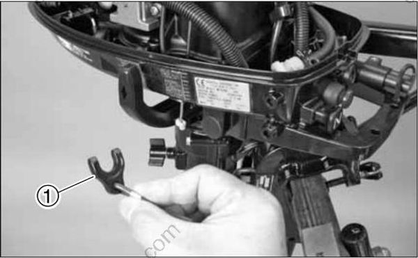
Start and run engine for 5 minutes to warm up, and then stop.
Shift gear into neutral (N).
Remove lock plate (1) (of stop switch lanyard) from stop switch.
Remove lock plate (of stop switch lanyard) from stop switch before measuring compression pressure. This will prevent engine from accidental starting.
- Remove all plug caps and then all spark plugs.
Clean areas around spark plugs on the cylinder before removing spark plugs to prevent dirt from entering cylinder.
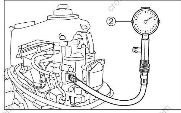
- Install compression gauge (2) to plug hole.
Compression Gauge (2) : Use commercially available item.
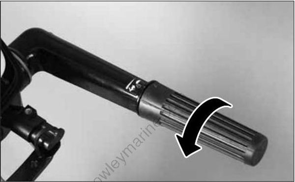
- Fully open throttle, crank engine until compression gauge (2) indication stabilizes, and then measure compression pressure.
Compression Pressure (Reference) : 500 r/min
With decompressor : 0.34 MPa (49.3 psi) [3.5 kgf/cm2] ±10%
Without decompressor : 0.93 MPa (137.8 psi) [9.5 kgf/cm2] ±10% (*Remove Exhaust rocker arm)
· Compression pressure is affected much by cranking speed, and normally changes approximately 10%.
· Do not pull choke knob when measuring compression pressure.
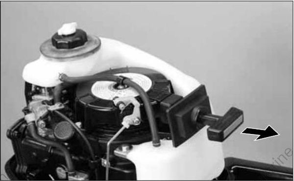
- If compression pressure is below specified value, put small amount of engine oil into cylinder, and perform the test again.
· If compression pressure increases after the above measure, check pistons and piston rings for wear. Replace if necessary.
· If compression pressure does not increase after the above measure, check valve clearances, valves, valve seats and cylinder head. Adjust or replace if necessary.
12) Inspection and Adjustment of Valve Clearance
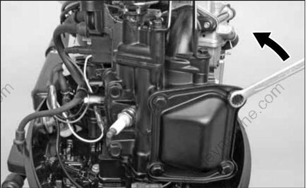
· Perform inspection and adjustment of valve clearances when engine is cold.
· #1 Set piston to top dead center of compression stroke.
- Remove cylinder head cover, fuel pump and spark plug.
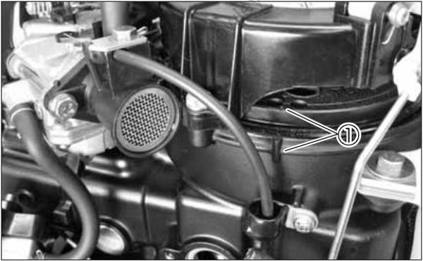
- Align locating marks (1) of flywheel and crankcase with each other.
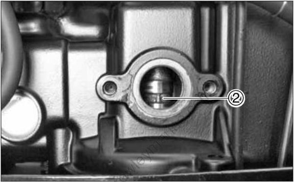
- When fuel pump is removed, cam shaft can be seen. If projection (2) of cam shaft can be seen, it can be known that the piston is at top dead center.
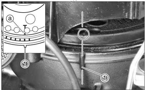
- The piston is at top dead center of compression stroke when locating marks (1) of flywheel (a) and cylinder that are found on the starboard side of crank case are aligned with each other.
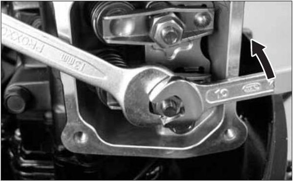
- Hold pivot and loosen lock nut.
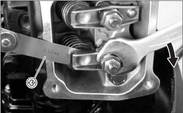
- Put thickness gauge (3) in the gap between rocker arm and valve.
Valve Clearance (when engine is cold) :
(IN) intake side : 0.06 - 0.14mm (0.0025 - 0.0055in)
(EX) exhaust side : 0.11 - 0.19mm (0.0045 - 0.0075in)
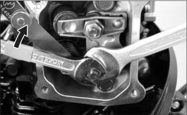
- Rotate pivot to adjust valve clearance, and then, tighten lock nut.
Pivot Adjust Nut : 10 N · m (7 lb · ft) [1.0 kgf · m]
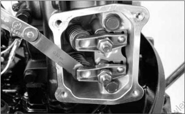
- Check valve clearance again.
13) Throttle Cable

Adjustment of Throttle Cable
- Check position of cable at low speed and high speed sides.
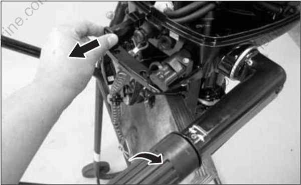
- Set throttle grip to slowest position, and fully pull choke knob to close choke valve.
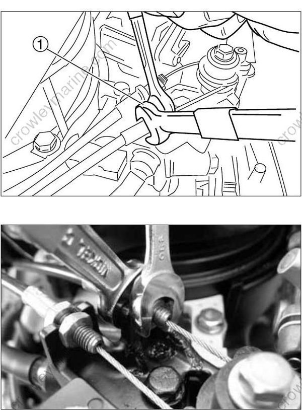
- Lock nut (1) while applying tension to outer wire by pulling it with a hand to fix low speed side wire.
The wire is in proper state if pushing inner wire at the center makes deflection of about 1mm.
- Repeat above steps for high speed side wire, and fix it.
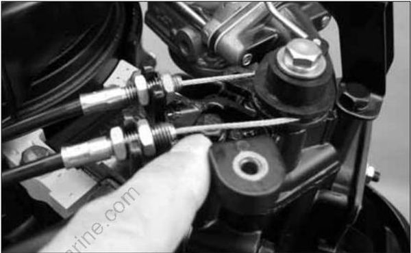
- Return choke knob to home position to fully open choke valve.
To confirm slowest position of throttle grip, check gap between projection of throttle drum and dent of opener section. The gap is acceptable if it is in the range between 0.5mm and 1mm.
Repeat steps 2. to 4. if necessary.
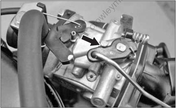
- Set throttle grip to full-open position, and check if throttle lever of carburetor makes contact with stopper.
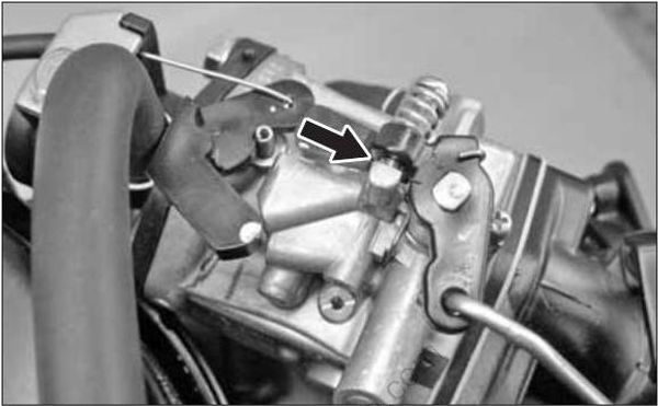
- Set throttle grip to full-close position, and check if throttle lever of carburetor makes contact with stopper.
14) Inspection of Idle Engine Speed
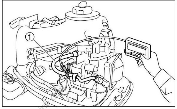
- Start engine and run for 5 minutes to warm up.
- Attach tachometer to spark plug high tension cord (1) to check idle speed.
More accurate and stable reading can be obtained when tachometer lead is connected with high tension cords of individual cylinders linked with each other.
Tachometer : Use commercially available item.
Idle Speed : 1300 r/min
15) Inspection of Ignition Timing
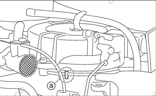

Adjusting system : Automatic control, no adjustment required Run engine and use timing light to check ignition timing.
8 timings marks are found on the side of flywheel (TDC0°, ATDC5°, BTDC5°, 10°, 15°, 20°, 25°, 30°), and ignition timing is read with mark on the center of starter case (a) window.
| Model | Range of Ignition Angle | Engine Starting | Idling | Accelerating |
|---|---|---|---|---|
| 4R/6R | TDC 0° — BTDC 25° | TDC 0° | TDC 0° | BTDC 25° |
16) Inspection of Anode
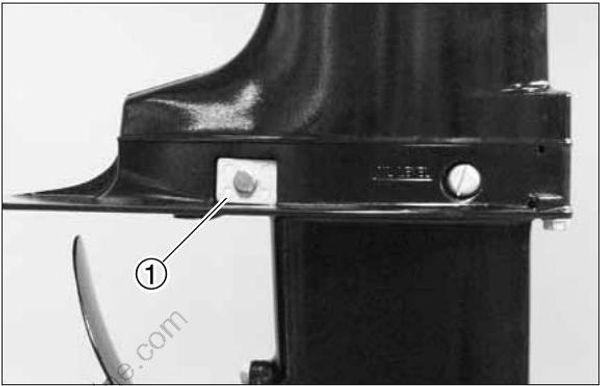
Replace anode (1) if it is corroded excessively.
Replace anode if volume is reduced to 2/3 of new part.
Do not coat anode and trim tab with oil, grease or paint, or the anti-corrosion function does not work normally.
· Do not coat anode with oil or paint.
· Since periphery of anode installation bolt is corroded more than other areas, be sure to retighten bolt at every inspection.
17) Replacement of Anode
Anode protects outboard motor from galvanic corrosion (corrosion of metal due to very weak electric current).
Anodes are used in the gear case, clamp bracket (PT models), and power unit cylinder.
Replace anode if volume is reduced to 2/3 of new part
· Do not coat anode with oil or paint.
· Since periphery of anode installation bolt is corroded more than other areas, be sure to retighten bolt at every inspection.
18) Inspection of Propeller
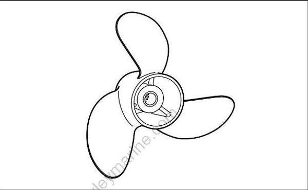
- Check propeller blades and spline for cracks, damages, wear and corrosion. Replace if necessary.
19) Inspection of Thermostat
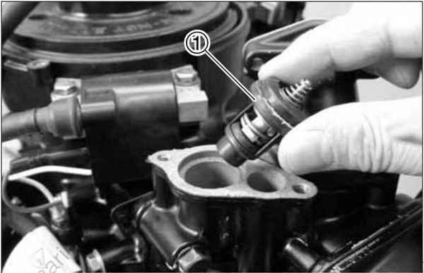
- Loose thermostat cover nut and remove thermostat (1).
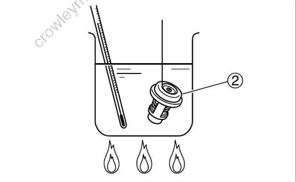
Hang thermostat (2) in the water container.
Put thermometer in the water, warm up water and measure water temperature when valve opens.
Put a piece of thread in the closed valve gap and hang it in the water. Valve opening moment can be known when thermostat is released to drop due to opening with rise of temperature.
Valve Opening Temperature : 50 - 54°C (121 - 129°F) (Valve starts to open at this temperature.)
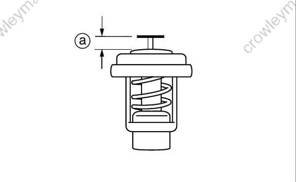
- Measure valve lift of thermostat when prescribed temperature has been reached. Replace if the length is less than specified value.
Water Temperature : 63 - 67°C (146 - 154°F)
Valve lift (a) : 3.0mm (0.12in) or over
- Install thermostat, new gasket and cover.
Thermostat Cover Bolt : 6 N · m (4 lb · ft) [0.6 kgf · m]
20) Inspection of Cooling Water Passage
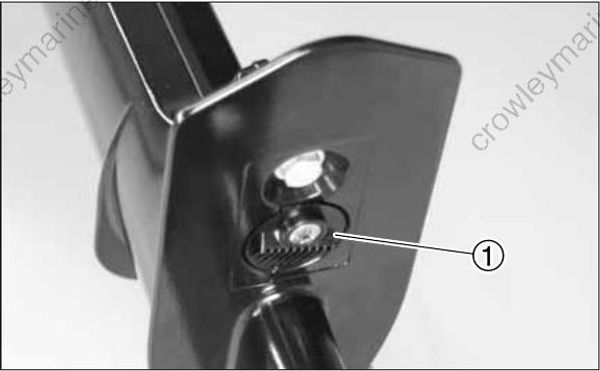
- Check water strainer (1) for clogging. Clean if necessary.
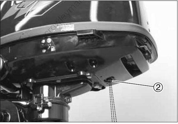
Set outboard motor in the water and start engine.
Check that cooling water is discharged from cooling water check port (2). If not, check water pump and cooling water passage in the engine.
21) Flushing with Water
Touching rotating propeller could lead to injury. Be sure to remove propeller before running engine on the land.
Exhaust gas contains carbon monoxide, which will cause gas poisoning. Do not start engine with outboard motor placed in a closed area such as boat house.
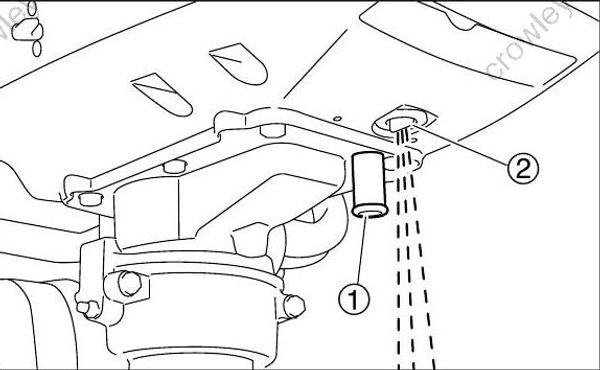
Flushing with water
Remove propeller and thrust holder.
Attach optional flushing attachment (1).
Cover water strainer with tape.
Put water hose on flushing attachment (1) and run water.
Set gear shift to neutral (N) and start engine.
Check that cooling water check port (2) discharges water, and run engine for 3 to 5 minutes at low speed.
Stop engine and stop water supply, remove flushing attachment (1), remove tape, and then, reinstall propeller.
22) Greasing Points
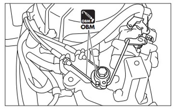
- Apply grease to throttle cable and sliding areas.
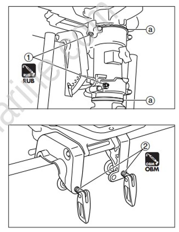
- Apply grease through grease nipples (1) until excessive grease appears from bushing (a).
Apply grease to thread of clamp screws (2).
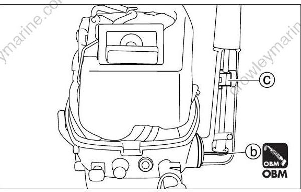
(c) Do not lubricate here.
- Apply grease to throttle cable (b) and sliding areas.
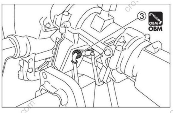
- Thinly apply grease to spring (3) of tilt stopper.
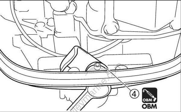
- Apply grease to seal ring and bushing (4) of hook lever.
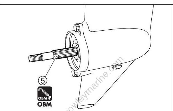
- Apply grease to propeller shaft spline (5).
