

1) Draining Gear Oil
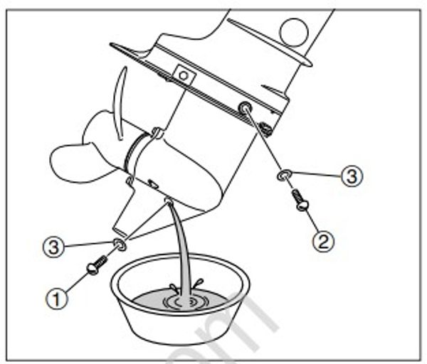
(3) Gasket Do not reuse.
- Remove oil plugs (2) and then (1) to drain gear oil. Refer to "Replacement of Gear Oil" in Chapter 3.
Remove lower oil plug (1) first.
2) Removing Propeller
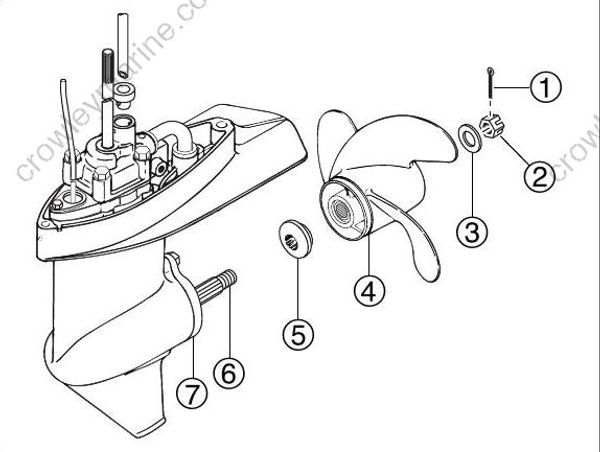
(1) Split Pin
(2) Propeller Nut
(3) Washer
(4) Propeller
(5) Thrust Holder
(6) Propeller Shaft
(7) Propeller Shaft Housing
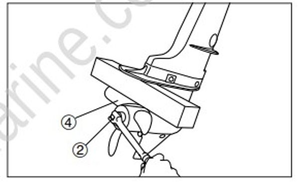
- Shift into reverse (R).
- Put a piece of wooden block between anti-cavitation plate and propeller (4) to prevent rotation of propeller (4), and then remove propeller nut (2) and then propeller (4).
· Before removing or installing propeller, be sure to disconnect spark plug cap and remove stop switch lock plate.
· When removing or installing propeller, do not handle propeller with bare hands.
· Put a piece of wooden block between anti- cavitation plate and propeller to prevent rotation of propeller.
3) Removing Lower Unit
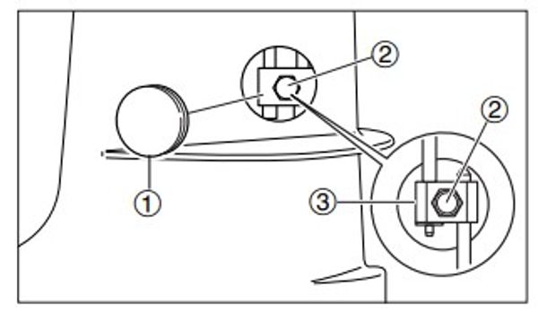
Removal of lower unit does not require removal of power unit from outboard motor body. Tilt up and lock with tilt stopper. Shift in reverse.
- Remove grommet (1) and loosen bolt (2).
Bolt (2) should be loosened, not removed from joint (3).
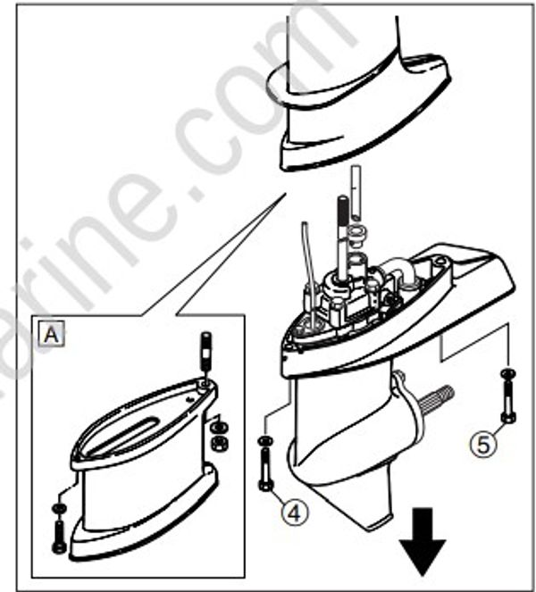
[A] UL-Transom Model
- Remove lower unit installation bolts (4) (5), and pull lower unit ass'y downward to remove.
Check drive shaft spline (a) for adhesion of oil, rust and wear.
4) Disassembly of Water Pump
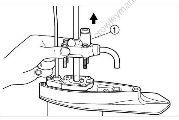
- Remove bolts, then remove pump case (upper) (1).
When removing or attaching water pump and pump case (lower), be careful that the drive shaft is not pushed up.
Pushing up the drive shaft causes pinion (B) to drop into the gear case.
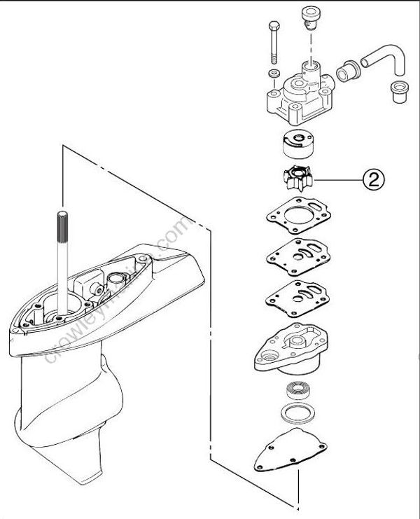
- Remove impeller (2).
5) Inspection of Water Pump
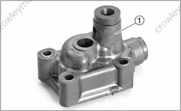
- Check pump case (upper) (1) for deformation. Replace if necessary.
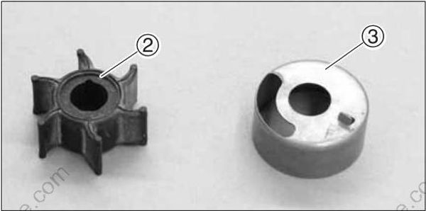
- Check impeller (2) and pump case liner (3) for crack and wear. Replace if necessary.
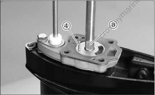
- Check key (4) and drive shaft installation face (a) for wear. Replace if necessary.
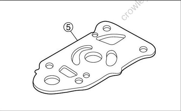
- Check water pump guide plate (5) for cracks and wear. Replace if necessary.
6) Removing Propeller Shaft Housing Ass'y
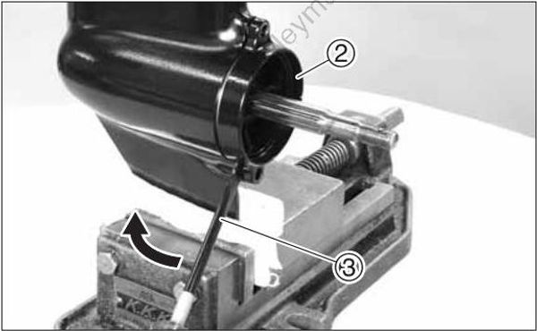
- Remove bolts (1) and pull out propeller shaft housing ass'y (2).
When the ass'y is pulled out a little, put bladed screw driver (3) in the mating surface of lower gear case to separate it from the case.
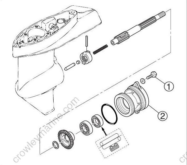
- Remove propeller shaft ass'y.
7) Disassembly of Propeller Shaft Housing
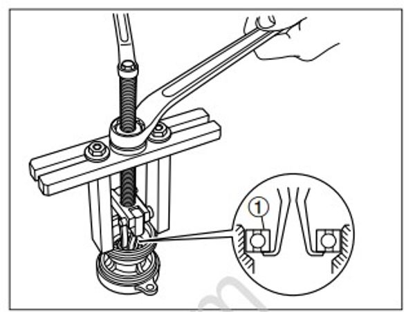
(1) Bearing Do not reuse
- Remove bearing (1) by using commercially available bearing puller.
Before removing, check bearing for play or deflection. Replace if necessary.
Do not reuse removed bearing.
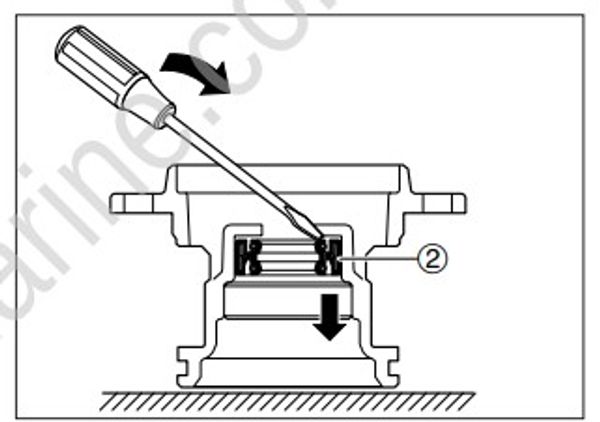
(2) Oil Seal Do not reuse.
- Remove oil seal (2).
8) Inspection of Propeller Shaft Housing
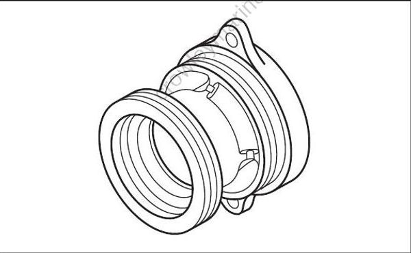
- Use cleaning oil and cleaning brush to clean propeller shaft housing, and check it for crack or damage. Replace if necessary.
- Check reverse (C) gear teeth and clutch for crack or damage. Replace if necessary.
When reusing bearing without removing it, check it for play or deflection. Replace if necessary.
9) Assembly of Propeller Shaft Housing
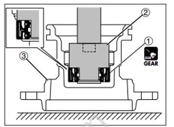
(1) Do not reuse
- Apply gear oil to outside of new oil seal (1), and attach it to propeller shaft housing (3) by using a commercially available mandrel (2).
GEAR

(4) Do not reuse.
- Install new bearing (4) to propeller shaft housing (3).
Do not reuse removed bearing.
Bearing Attachment 2 (5) : P/N. 5041789
Driver Rod 3 (6) : P/N. 5041762
GEAR
- Apply OBM grease to lip of oil seal (1).
OBM
10) Removing Drive Shaft
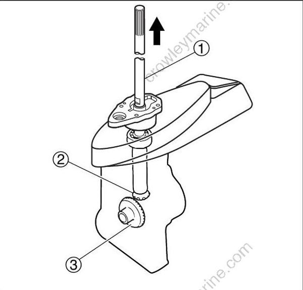
- Pull up pump case (lower) and drive shaft ass'y (1), remove pinion (B) gear (2), and then pull out forward (A) gear (3).
· When removing forward (A) gear (3), be careful not to damage the existing shims or lose them. Shim is reusable.
· Replace shim with new one of the same thickness if any deformation or damage is found on it.
11) Disassembly of Propeller Shaft Ass'y
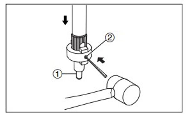
- Pull out clutch pin (2) while pushing push rod (1). Remove clutch (3), push rod (1), spring retainer (4), and spring (5).
· Take care not to allow parts to fly out by easing spring tension gradually.
· Do not reuse removed clutch pin.
Spring Pin Tool A : P/N. 5041751
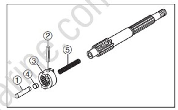
- Check clutch (3), spring retainer (4), ball, and push rod (1) for crack and wear. Replace if necessary.
12) Inspection of Propeller Shaft
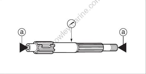
(a) Support point
- Check propeller shaft for bend and wear. Replace if necessary.
- Measure propeller shaft runout.
Runout Limit (a) (Max) : 0.05 mm (0.0020 in)
13) Assembly of Propeller Shaft Ass'y
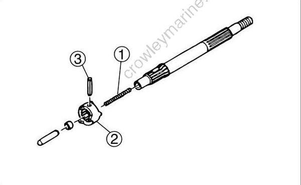
- Fix propeller shaft with vice, and install spring (1) and clutch (2).
· Assemble parts with clutch and propeller shaft holes aligned with each other.
· Set spring pin with groove directing 90 degrees from axial direction of propeller shaft.
· Apply gear oil before assembling.
· Use vice jaw protectors or wood to protect propeller shaft from damage from vice.
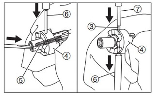
- Using bladed screw driver, shorten spring (1) by referring to illustration, insert spring pin tool A (4) into hole of clutch (2) to secure spring. Slowly press fit new spring pin (3) from the other side, putting it on the spring pin tool A and by using spring pin tool B (5).
Do not reuse removed spring pin.
· Drive spring pin into clutch hole to depth of approximately 0.5mm from the surface.
· After setting spring pin, check operations of clutch.
Spring Pin Tool A : P/N. 5041751
Spring Pin Tool B : P/N. 5041753
14) Removing Clutch Cam and Cam Rod
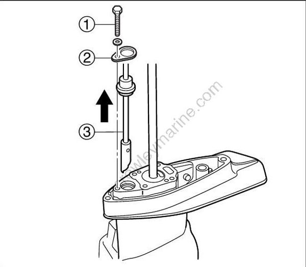
- Remove bolt (1), stopper (2), and then pull cam rod ass'y (3) upward to remove.
15) Disassembly of Clutch Cam and Cam Rod
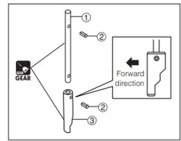
(2) Do not reuse.
- Remove spring pins (2) and clutch cam (3) from cam rod (1).
· Use spring pin tool A to remove spring pins.
· Do not reuse removed spring pins.
Spring Pin Tool A : P/N. 5041751
16) Inspection of Clutch Cam and Cam Rod
17) Assembly of Clutch Cam and Cam Rod
- Install clutch cam (3) and spring pin (2) to cam rod (1).
Spring Pin Tool B : P/N. 5041753
Be careful of direction of cam rod.
18) Removing Pump Case (Lower)
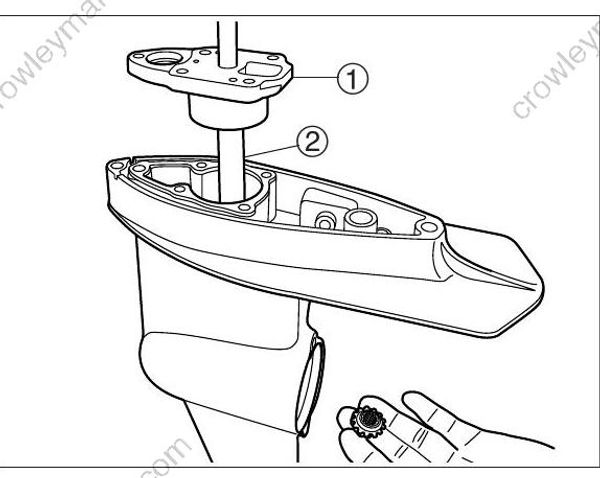
- Remove pump case (lower) (1) and drive shaft (2) while holding pinion (B) gear with hand.
Pinion gear (B) will drop into gear case when drive shaft is removed.
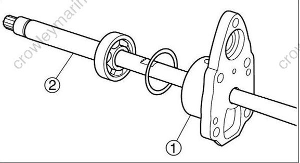
- Remove forward (A) gear from gear case.
- Remove pump case (lower) (1) from drive shaft (2).
19) Disassembly of Pump Case (Lower)
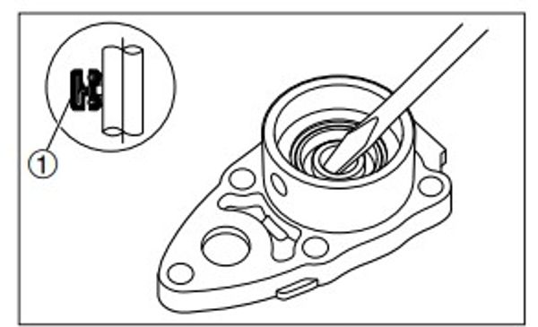
(1) Do not reuse.
- Use bladed screw driver to remove oil seal (1).
20) Assembly of Pump Case (Lower)
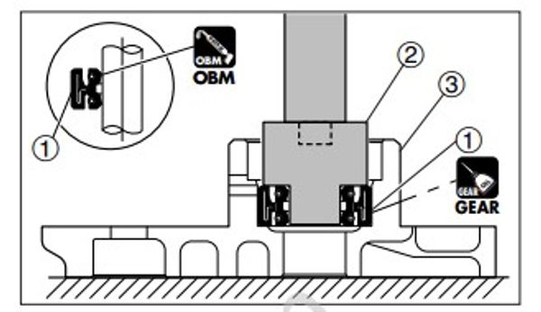
(1) Do not reuse.
- Apply gear oil to outside of new oil seal (1), and attach it to pump case (lower) (3) with numbered side down by using a commercially available mandrel (2).
GEAR
- Apply OBM grease to lip of oil seal (1).
OBM
21) Inspection of Drive Shaft
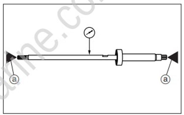
(a) Supporting Points
Check drive shaft for bend and wear or twisted splines.
Replace if necessary.
Measure drive shaft runout.
Runout Limit (Max) : 0.2 mm (0.008 in)
22) Inspection of Pinion (B) Gear and Forward (A) Gear
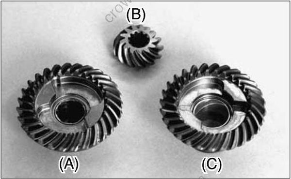
- Check pinion (B) gear, forward (A) gear, reverse (C) gear teeth and clutch for crack and wear. Replace if necessary.
23) Disassembly of Gear Case
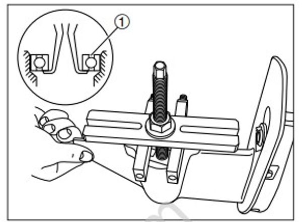
(1) Do not reuse
- Check bearings (1) for cracks and generation of abnormal noise. Replace if necessary.
Do not reuse removed bearing.
· Do not remove bearing unless it is replaced with new one.
· Before removing, check bearing for play or deflection. Replace if necessary.
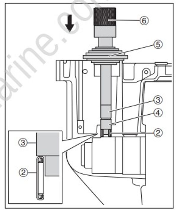
(2) Do not reuse
- Remove bearing (1) by using commercially available bearing puller.
- Remove bearing (2).
Needle bearing press Ass'y (7) : P/N. 5041756
Center Plate 3 (5) : P/N. 5041757
Driver Rod 3 (6) : P/N. 5041762
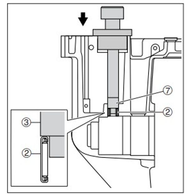
Needle bearing press Ass'y (7) : P/N. 5041756
24) Inspection of Gear Case
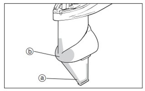
- Check skeg area (a) and torpedo-like front area (b) for cracks and damage. Replace if necessary.
25) Assembly of Gear Case
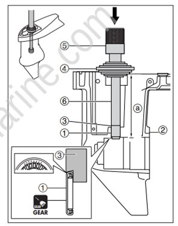
(1) Do not reuse
Do not reuse removed bearing.
- Install bearing (1) with numbered side up to gear case (2) to specified depth.
Installation Depth (a) : 100 mm ± 0.15 mm (3.9370 in ± 0.0059 in)
If a special tool is not available and thus the above depth cannot be maintained, order gear case ass'y.
GEAR
Needle bearing press Ass'y (6) : P/N. 5041756
Center Plate 3 (4) : P/N. 5041757
Driver Rod 3 (5) : P/N. 5041762
Needle bearing press Ass'y (6) : P/N. 5041756
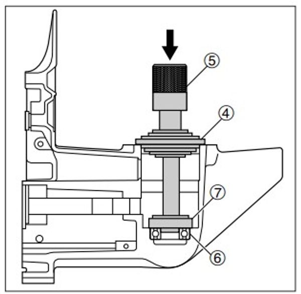
(6) Do not reuse
- Install new bearing (6) with numbered side up.
Bearing Installer 4 (7) : P/N. 5041760
Center Plate 3 (4) : P/N. 5041757
Driver Rod 3 (5) : P/N. 5041762
26) Installation of Forward Gear and Pinion Gear (A and B Gears)
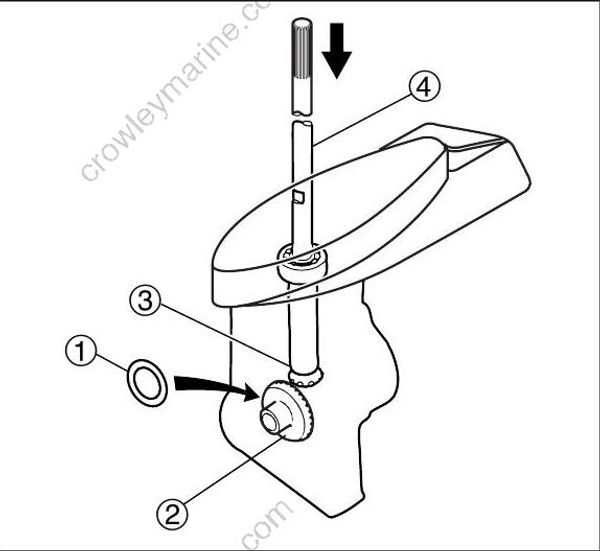
Install shim (1) and forward (A) gear (2) that were removed previously.
Install pinion (B) gear (3) and drive shaft ass'y (4).
Replace shim with new one of the same thickness if any deformation or damage is found on removed shim.
- When replacing shims placed between forward (A) gear and bearing, measure thickness of original shims and use shims with the same thickness.
Sizes of Adjusting Shims : For pinion (A) gear side : 0.1, 0.15mm Since the shims are for canceling machining error, use the ones with thickness of original parts.
27) Reassembly of Pump Case (Lower)
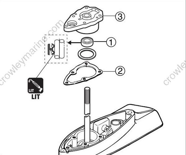
(2) Do not reuse.
- Apply grease to lip of oil seal (1) after installing it.
UT
- Attach new O-ring (2) and pump case (lower) (3).
28) Installation of Clutch Cam and Cam Rod
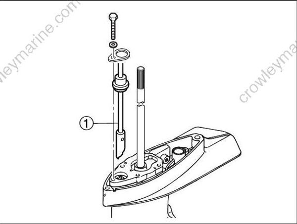
- Install cam rod ass'y (1) to gear case as shown.
Be careful of direction of cam rod.
29) Determination of forward (A) gear backlash
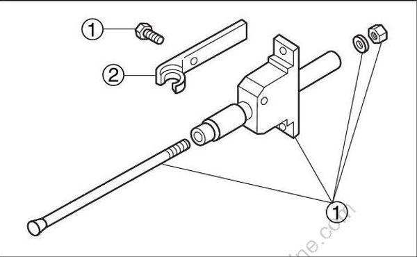
Backlash Measuring Tool Kit : P/N. 5041773
Backlash Measuring Tool Ass’y (1)
Measuring Tool Set Piece (2)
Clamp A : P/N. 5041775
Dial Gauge Plate : P/N. 5041776
(4) Pump Case
(5) Pinion (B) Gear
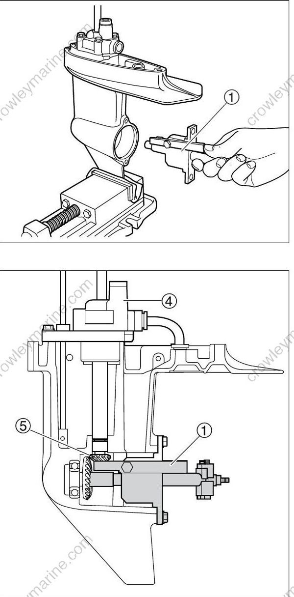
Perform measurement of backlash between forward (A) gear and pinion (B) gear with propeller shaft housing, propeller shaft and reverse (C) gear removed from gear case.
- Install pump case (4) to gear case, and assemble backlash measuring tool (1) as illustrated.
· Fix gear case with vice.
· Clean drive shaft with new rag before assembling the tool.
· Assemble all parts of pump case except impeller and key, and tighten to specified torque.
· Perform measurement of backlash between forward (A) gear and pinion (B) gear with propeller shaft housing, propeller shaft and reverse (C) gear removed from gear case.
Proper Backlash Obtained from Gauge Reading : 0.16 - 0.49mm (0.0063 - 0.0193 in)
Sizes of Adjusting Shims : For Pinion (B) Gear Side : 0.1, 0.15mm
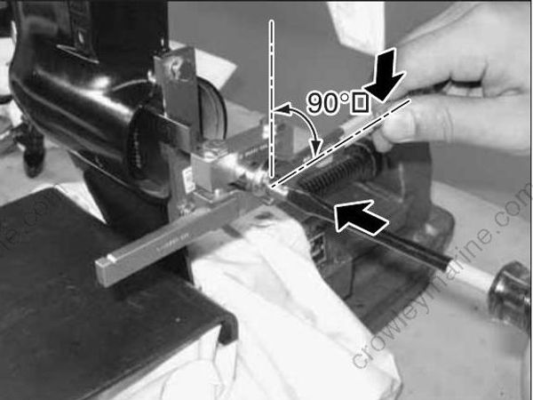
- First, pull up drive shaft by using hand.
Fix shaft B with bladed screw driver, and tighten nut while pushing the shaft. At this time, be careful not to overtighten the nut, or shaft B is locked.
Tighten nut fully by using fingers, and then, additionally tighten approximately 90 degrees by using spanner wrench. During the work, fix shaft B by using bladed screw driver.
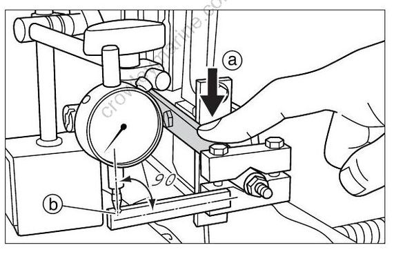
- Secure clamp halves A and B to shaft B using bolts. Move clamp A while pushing arm in direction (a), and read dial gauge at notch groove (b) position.
Proper Backlash Obtained from Gauge Reading : 0.16 - 0.49mm (0.0063 - 0.0193 in
Sizes of Adjusting Shims : For Pinion (B) Gear Side : 0.1, 0.15m
- Perform shim adjustment at pinion (B) gear side as necessary based on the gauge value obtained. The table shows relation between dial gauge readings and shim adjustments.
1.Values in this table indicate dial gauge readings that are obtained when using special tool.
2.Change gear engagement position and measure backlash again for check.
| Gauge Reading mm | Shim Adjustment mm |
|---|---|
| 0.00 - 0.15 | -0.10 |
| 0.16 - 0.49 | 0 |
| 0.50 - 0.52 | +0.25 |
| 0.53 - 0.59 | +0.30 |
| 0.60 - 0.65 | +0.35 |
| 0.66 - 0.71 | +0.40 |
| 0.72 - 0.77 | +0.45 |
30) Installation of Water Pump
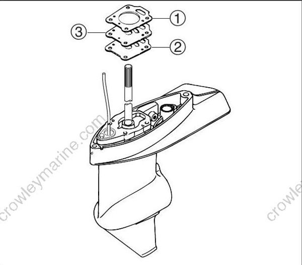
(1)(2) Gasket Do not reuse
- Attach new gaskets (1) and (2), water pump guide plate (3) and dowel pin.
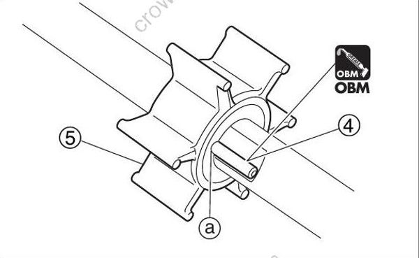
Attach key (4) to drive shaft.
Bring impeller (5) groove (a) to key (4) and install impeller to drive shaft.
· When reusing impeller, install it so that it rotates in original direction.
· Apply grease to the key to prevent it from dropping when attaching.
OBM
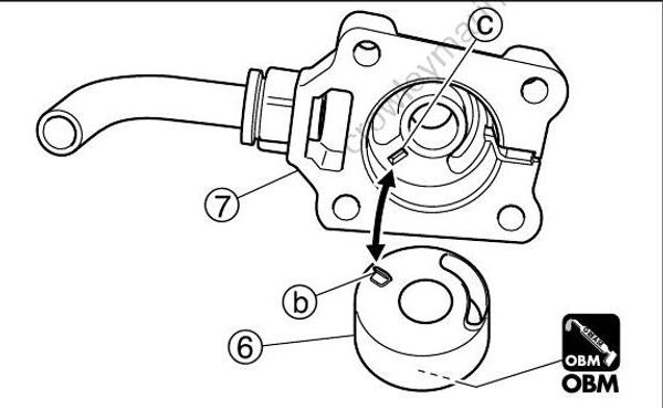
- Attach pump case liner (6) to pump case (upper) (7), and apply grease to interior of pump case liner (6).
Bring pump case liner projection (b) to pump case (upper) groove (c).
OBM
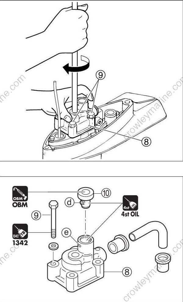
- Install pump case (upper) ass'y (8) on the gear case, and tighten bolts (9) in two or three steps to specified torque.
Apply grease to interior of pump case liner, and install pump case (upper) by pushing it down with hand while turning drive shaft clockwise.
Pump Case (Upper) Bolts (9) : 6 N · m (4 lb · ft) [0.6 kgf · m]
OBM
- Bring grommet (10) projection (d) to hole (e), and install it to pump case (upper) ass'y (8).
4st OIL
OBM
1342
31) Installation of Propeller Shaft Housing
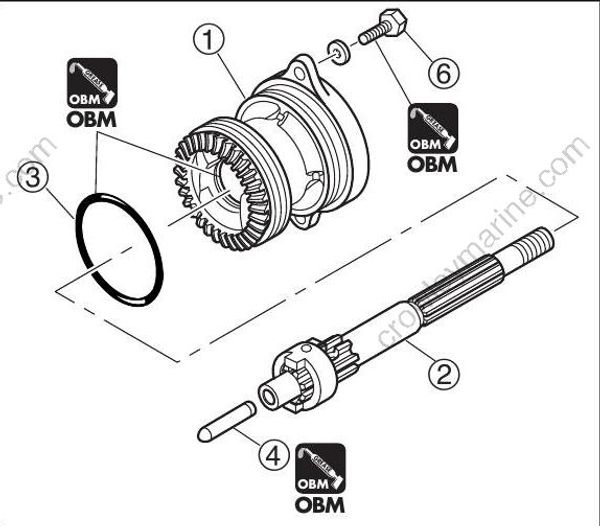
Check that OBM grease is applied to lip of oil seal of housing ass'y (1).
Install propeller shaft ass'y (2) to propeller shaft housing ass'y (1).
Apply grease to new O-ring (3) and install it.
Apply grease to clutch push rod (4) and install it to propeller shaft ass'y (2).
Attach propeller shaft housing ass'y (1) to gear case, and tighten bolts (6) to specified torque.
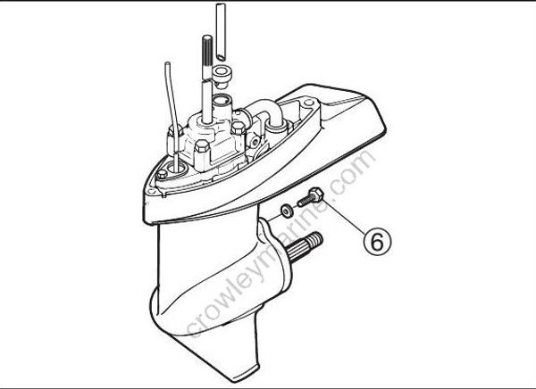
Propeller Shaft Housing Bolts (6) : 6 N · m (4 lb · ft) [0.6 kgf · m]
OBM
· Apply grease to clutch push rod to prevent it from dropping when attaching.
· When installing housing ass'y to gear case, tighten upper and lower bolts in 2 or 3 steps evenly to specified torque.
32) Filling with Gear Oil
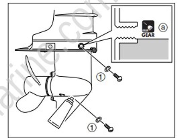
(1) Gasket Do not reuse
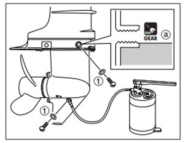
(1) Gasket Do not reuse
- Feed gear oil to specified quantity (a). "Refer to Chapter 3."
Perform "Inspection of Gear Case (Leakage)" in Chapter 3 if necessary
GEAR
33) Installation of Lower Unit
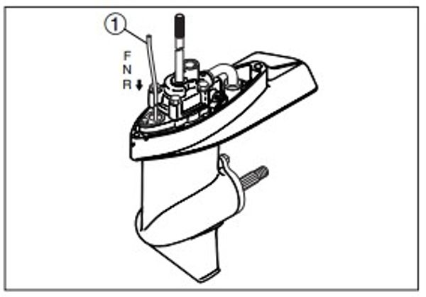
- Set cam rod (1) to reverse (R) position.
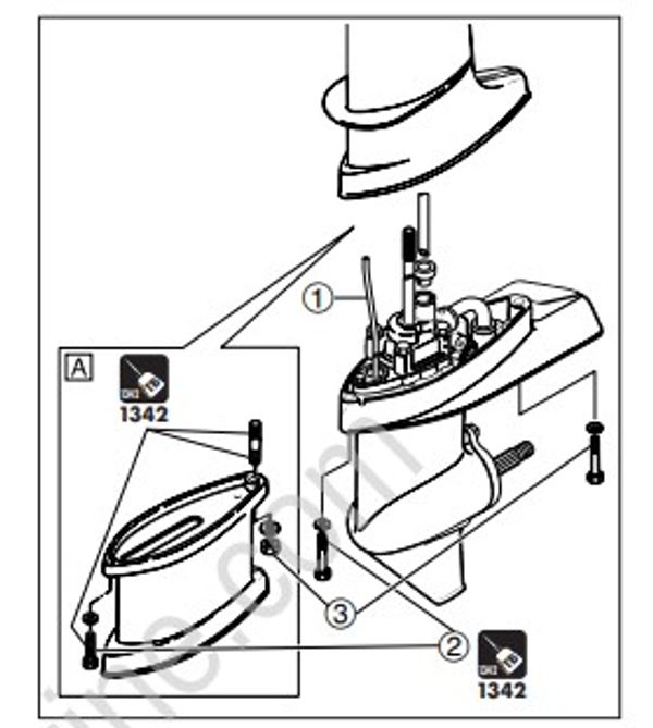
[A] UL-Transom Model
- Attach lower unit ass'y to drive shaft housing, and tighten lower unit installation bolts (2) (nut (3) ) to specified torque.
Connect water pipe securely. Move flywheel a little to align the drive shaft spline to crank shaft spline.
Lower Unit Installation Bolts (M8)(2) : 6 N · m (4 lb · ft) [0.6 kgf · m]
Lower Unit Installation Bolt, Nut (M8)(3) : 13 N · m (9 lb · ft) [1.3 kgf · m]
1342
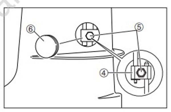
- Install cam rod (1) to joint (4) and tighten bolt (5) to specified torque.
Joint Bolt (5) : 6 N · m (4 lb · ft) [0.6 kgf · m]
- Attach grommet (6) to drive shaft housing.
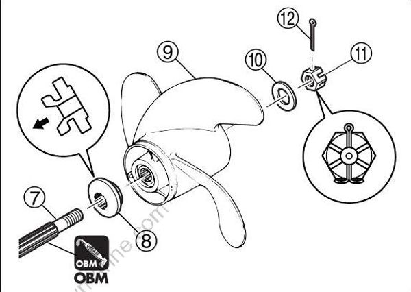
- Apply OBM grease to propeller shaft (7).
OBM
- Attach thrust holder (8) , propeller (9) , washer (10) and propeller nut (11) to propeller shaft. Put a piece of wooden block between anti-cavitation plate and propeller to prevent rotation of propeller, and tighten propeller nut to specified torque.
Before removing or installing propeller, be sure to disconnect spark plug cap and remove stop switch lock plate.
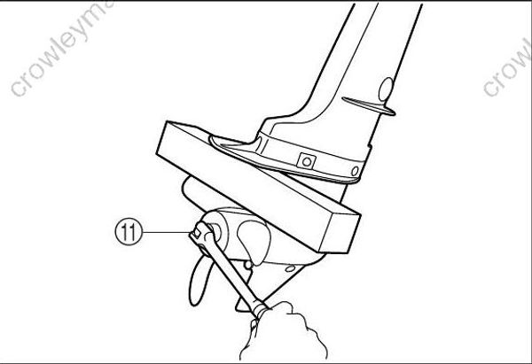
Turn propeller nut (11) to tightening direction to align one of grooves to propeller shaft hole, and attach split pin (12) .
Check gear oil level. "Refer to Chapter 3."
Perform "Inspection of Lower Unit (Air Leakage)" in Chapter 3 if necessary.
