

1) Removal and inspection of drive shaft housing
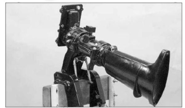
- Tilt up drive shaft housing.
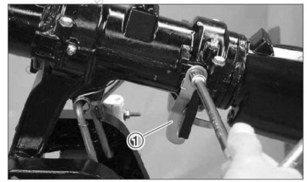
- Remove reverse lock arm (1).
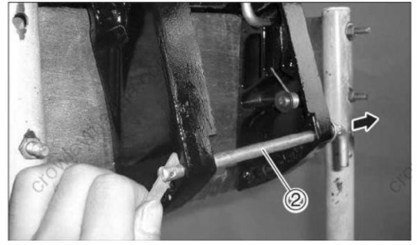
- Remove thrust rod (2).
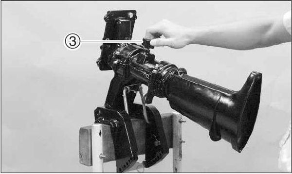
Remove wing nut (3) for co-pilot.
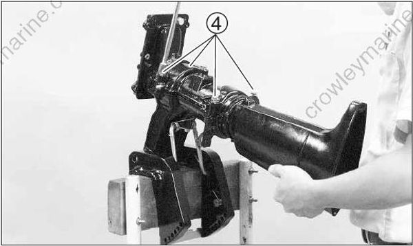
Loosed four swivel bracket (B) bolts (4).
Hold drive shaft to prevent it from dropping.
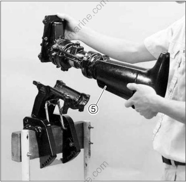
- Remove drive shaft housing (5).
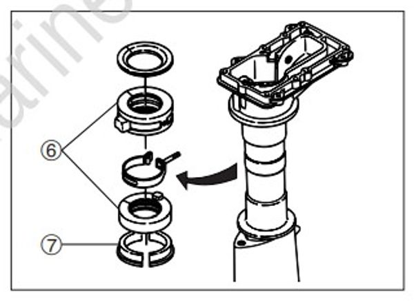
- Check steering bushing (6) and thrust place (7) for wear and damage, and replace if necessary.
2) Removal and inspection of clamp bracket
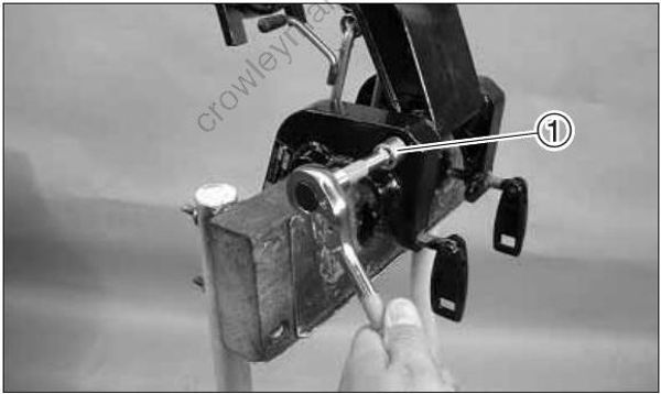
- Loosen clamp bracket mounting nut (1) and remove bolt.
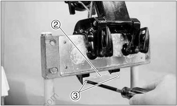
- Remove bracket distance place (2) mounting screws (3).
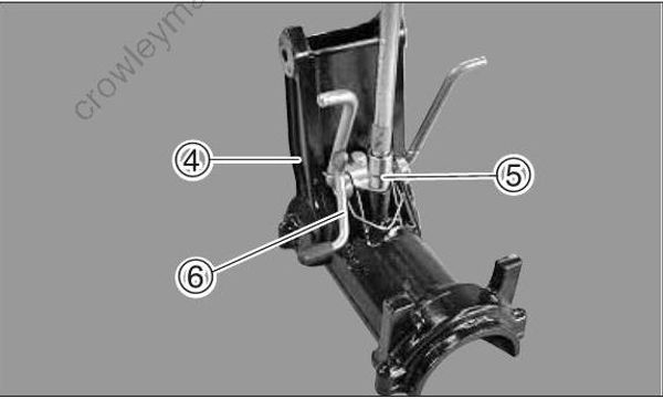
- Remove tilt stopper (5) mounting bolt (6) from swivel bracket (4), and then remove tilt stopper (5).
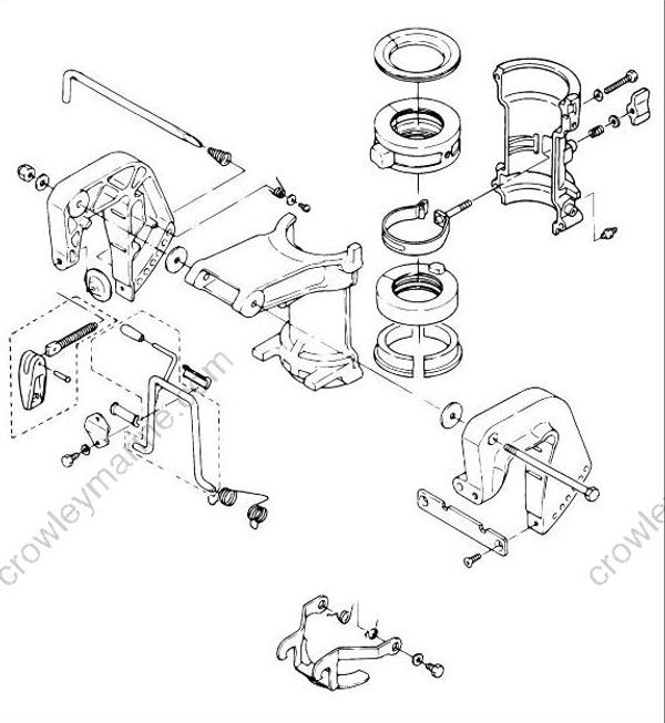
Check tilt stopper and bracket for damages.
Replace if damaged.
3) Installation of clamp bracket and drive shaft
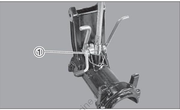
- Install tilt stopper (1) to swivel bracket (A).
Apply grease to sliding areas of tilt stopper.
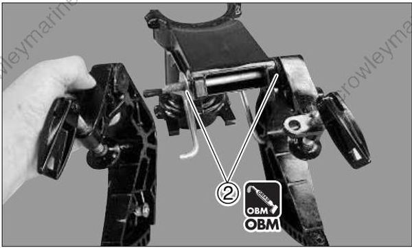
Install clamp bracket to swivel bracket (A).
Apply grease to both sides of washer (2).
OBM
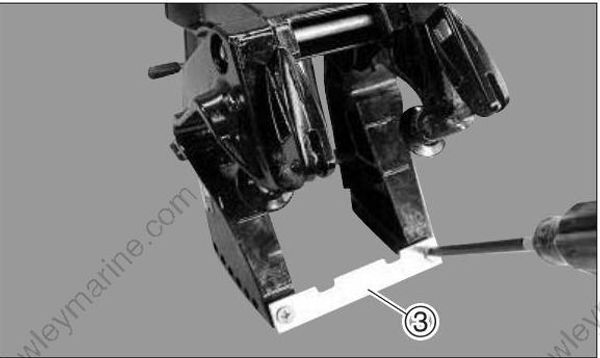
- Install distance plate (3) to clamp bracket.
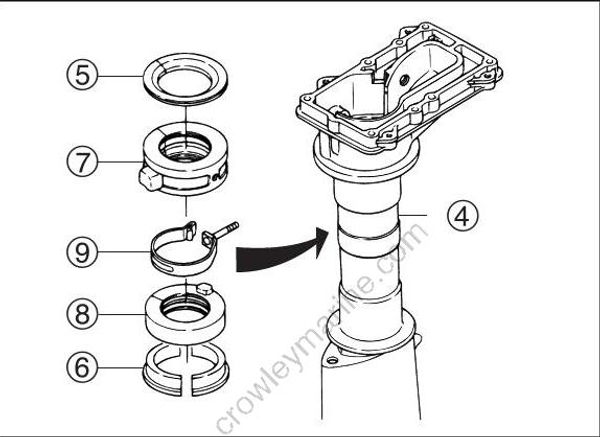
- Install thrust bushing (5) , thrust place (6) , steering bushings (7) and (8) and friction plate (9) on the drive shaft housing (4).
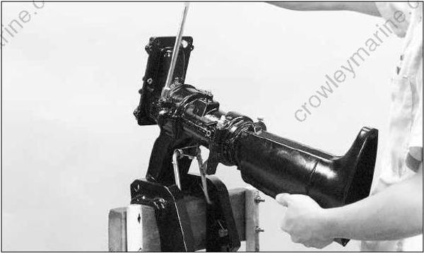
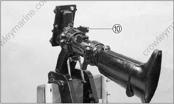
- Install drive shaft housing and swivel bracket (B) to swivel bracket.
Attach wing nut (10), and check operation of steering friction.
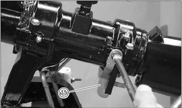
- Install reverse lock arm (11) on the swivel shaft.
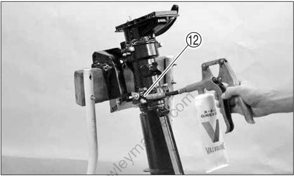
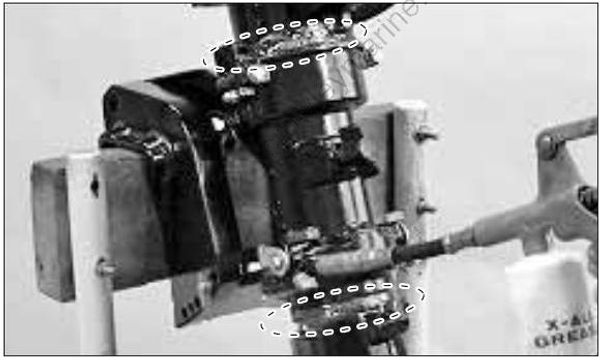
- Check operation of each part, and put grease through swivel shaft grease nipple (12).
Keep putting grease until excessive grease appears from thrust bushing.
OBM
4) Removal, inspection and installation of water pipe
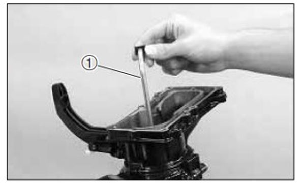
Remove water pipe (1) from drive shaft housing (2).
Check water pipe for crack and damage.
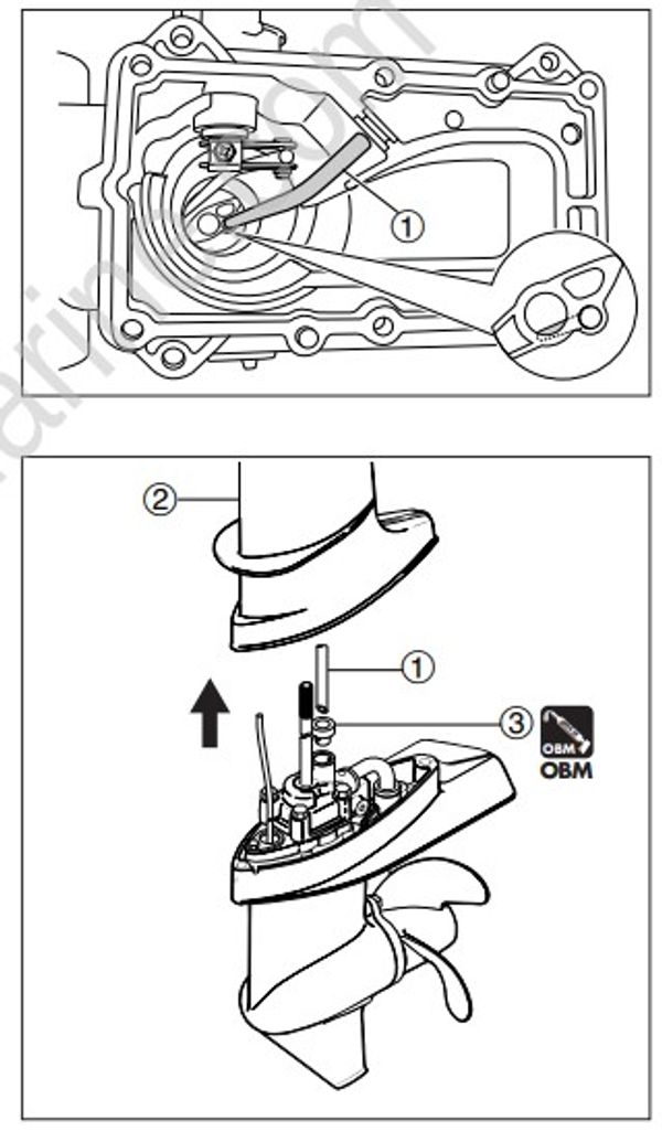
- Install water pipe (1) into drive shaft housing (2).
· Apply grease to water pipe grommet (3) before installation.
· Attach water pipe surely to drive shaft bushing
OBM
5) Remove, inspection and installation of tiller handle.
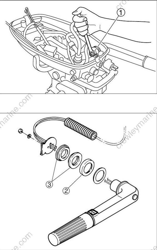
- Loosen stud bolt (1) of tiller handle, and remove tiller handle from bottom cowl.
- Check tiller handle spacer (2) and bushings (3) for wear and damage.
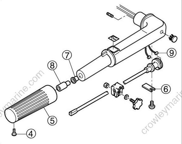
Loosen throttle grip screw (4) and remove the grip (5).
Remove throttle shaft supporter (6) screw.
Check bushing (7) and throttle shaft dumper (8) for damage.
- Check throttle wire (9) for break, bend and crack, and replace if necessary.
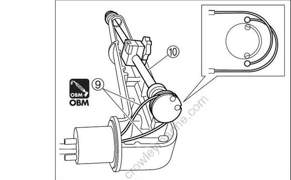
- Attach throttle wire (9) to throttle shaft (10) as shown.
OBM
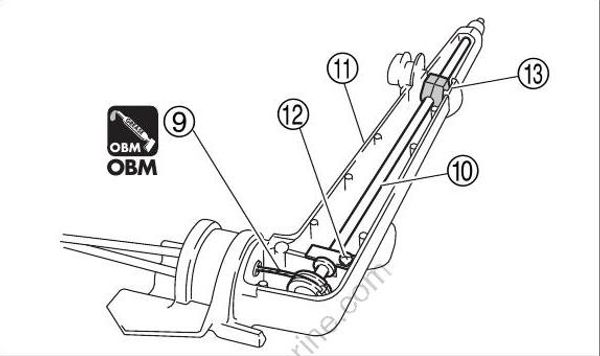
Attach throttle shaft (10) with throttle wire (9) to tiller handle (11), and tighten adjusting screw (12) securely.
Tighten throttle supporter.
Be careful of location of throttle friction (13).
OBM
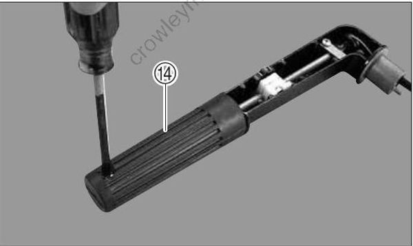
- Install throttle grip (14) to tiller handle, and secure with screw.
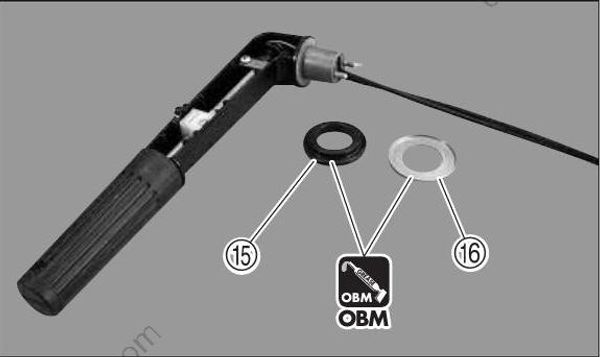
- Install tiller handle bushing (15) and spacer (16) to tiller handle.
Apply grease to tiller handle bushing (15) and spacer (16).
OBM
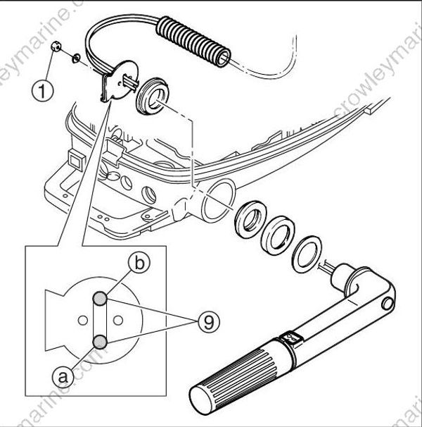
Install tiller handle to bottom cowl.
Tighten nut (1) to specified torque.
Tiller handle securing nut (1) : 6 N · m (4 lb · ft) [0.6 kgf · m]
Arrange throttle cable (9) as shown.
(a)< High speed side >, (b)< Low speed side >
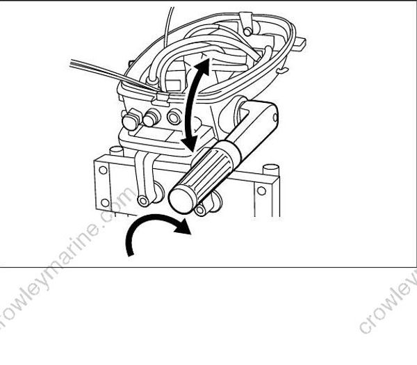
- Check operations of tiller handle and throttle grip.
6) Adjustment of Throttle Cable
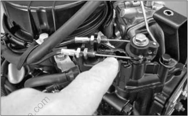
- Check position of cable at low speed and high speed sides.
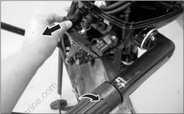
- Set throttle grip to slowest position, and fully pull choke knob to close choke valve.
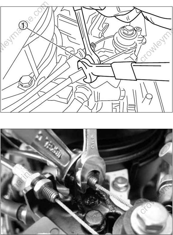
- Adjust lock nut (1) while applying tension to outer wire by pulling it with a hand to fix low speed side wire.
The wire is in proper state if pushing inner wire at the center makes deflection of about 1 mm.
- Repeat above steps for high speed side wire, and fix it.
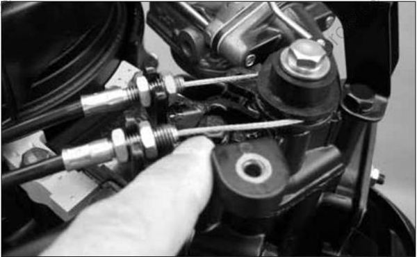
Return choke knob to home position to fully open choke valve.
To confirm slowest position of throttle grip, check gap between projection of throttle drum and dent of opener section. The gap is acceptable if it is in the range between 0.5 mm and 1 mm.
Repeat steps 2. to 4. if necessary.
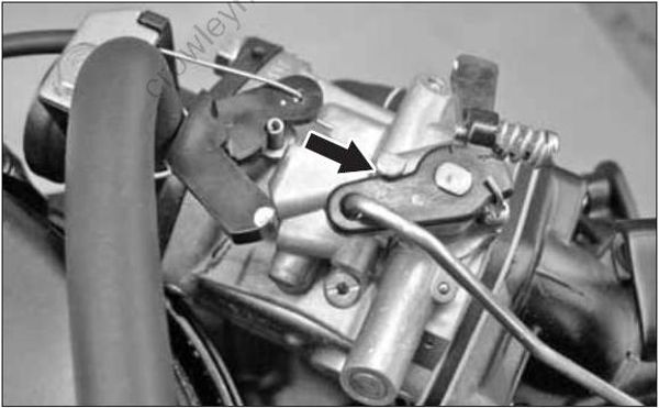
- Set throttle grip to full-open position, and check if throttle lever of carburetor makes contact with stopper.
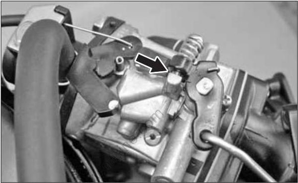
- Set throttle grip to full-close position, and check if throttle lever of carburetor makes contact with stopper.
