

LIFTING THE OUTBOARD
To avoid personal injury, make sure the lifting capacity of the hoist is at least twice the weight of the outboard. DO NOT all ow the lift hook or chain from the hoist to come in contact with any part of the engine during lifting.
Use correct Lifting Fixture to lift outboard:
| Model | Lifting Fixture |
|---|---|
| 90° V6 | P/N396748 with1 3/4 in. screws |
Place lifting tool on flywheel and seat the three screws completely.
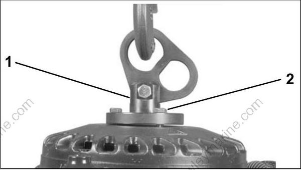
- Lifting fixture
- 1 3/4 in. screws
002419
Fasten appropriate chain hook to eye of too l. Carefully hoist outboard with chain and unbolt out board mounting brackets from frame.
OUTBOARD RIGGING CONNECTIONS
IMPORTANT: For complete outboard rigging and remote control installation information, refer to
the Pre delivery and Installation Guide included with the service manual set
Common Practices – All Models
Control Cable Identification
IMPORTANT: Identify control cable function before rigging outboard.
Identify each control cable:
• Put the control handle into NEUTRAL position.
The throttle cable casing guide will retract completely and the shift cable casing guide will go to the midpoint of its travel.
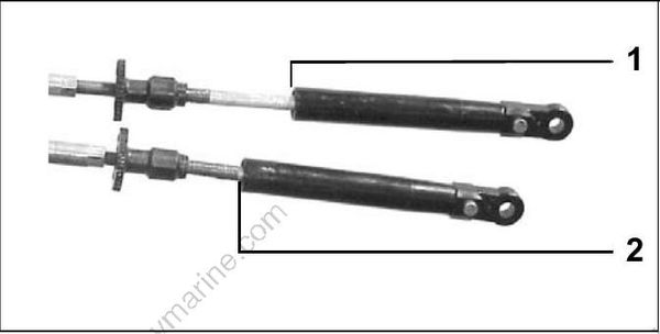
- Shift cable casing guide extended to midpoint
- Throttle cable casing guide retracted
DP0811
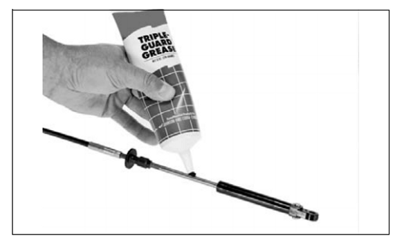
Extend the control cables and lubricate them with Triple-Guard grease.
30501
Cable Retainer Clip Installation
When installing retainer clips on control arm linkage pins, clips should be locked and must not be bent or deformed.
For proper installation, review the following steps:
• Place washer on pin.
• Position retainer clip with straight section on the bottom and angled section on the top.
• Use long nose pliers to insert straight section of clip into linkage pin hole.
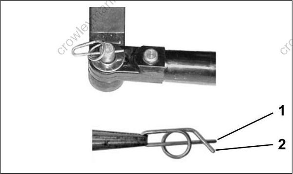
- Straight section
- Angled section
DP0818
DP0817
- Push the clip toward s t he h ole while lifting on the curved end with the pliers.
- Be sure retainer clip fully engages the pin.
- Lock the retainer by moving the angled section behind the straight section.
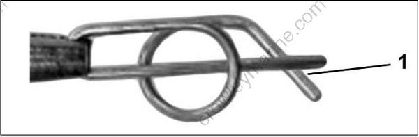
Locked Retainer Clip
- Angled section behind straight section
DP0817A
Cable, Hose, and Wire Routing
To prevent accidental starting while servicing, disconnect the battery cables at the battery. T wist and remove all spark plug leads.
Refer to Control Cable Identification on p. 17.Remove two screws and b racket that fasten t he grommet to lower motor cover.
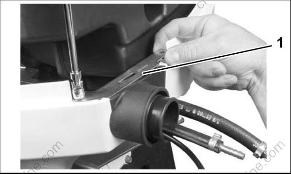
- Grommet retaining bracket
003964
Route all hoses, control cable s, and wiring through a protective sleeve or conduit into the boat and through the grommet.
The fuel hose may be routed through the protective sleeve or through an alternate hole in the lower motor cover grommet. To route the fuel hose outside the sleeve, trim the material cove ring the alternate fuel hose slot in the grommet.
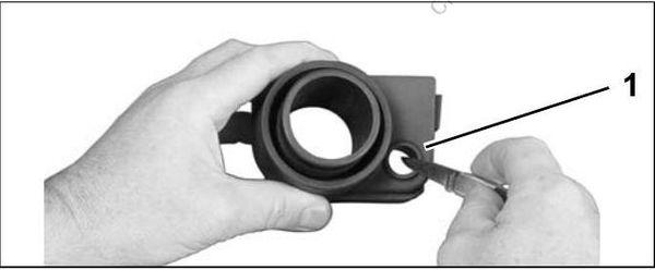
- Alternate fuel hose location
003970
Refer to the following diagram to ensure pro per positioning of rigging components in grommet.
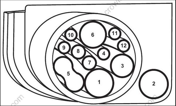
000095
- Fuel supply hose
- Fuel supply hose--alternate location
- Oil supply hose
- Oil tank sending unit harness
- Battery cables
- Main wire harness (MWS)
- Shift cable
- Throttle cable
- Accessory charge wires
- I-Command harness
- Water pressure hose
- Speedometer hose
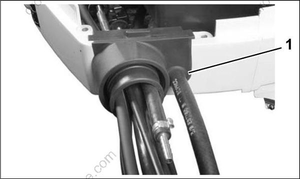
- Alternate fuel hose location
003971
The main wiring harness, battery cables, oil tank sending unit harness, and any ICON or I-Command network cables should be routed along the same path to the starboard side of the power head.
Secure all cables with clamps.
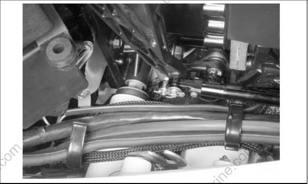
003974
After in stallation make sure there is enough clearance for all cables to avoid binding or chafing through all engine steering and tilting angles.
Control Cable Installation
Refer to Control Cable Identification on p. 17.Remove control cable trunnion covers and cable attachment hardware.
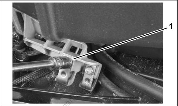
- Trunnion covers
005037
Shift Cable Installation and Adjustment Place t he shift cable on t he shift l ever p in and
install the washer and retainer clip. Refer to Cable Retainer Clip Installation on p. 18.
IMPORTANT: Do not bend or deform clip. Make sure the remote control, gear case, shift link age, and shift cable are in NEUTRAL. Hold the shift linkage in NEUTRAL.
Push and pull on the shift cable and observe the cable slack. Hold the casing guide in the center of the slack. Adjust shift cable trunnion to align with center of the trunnion b lock. Place cable trunnion in trunnion block. Install trunnion cover and screw. Tighten screw to a torque of 60 to 80 in. lbs. (7 to 9 N·m).
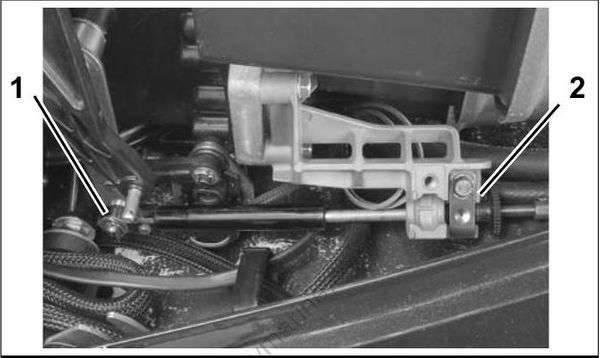
- Shift cable retainer clip and washer
- Shift cable trunnion
005038
Throttle Cable Installation and Adjustment
With remote control lever in NEUTRAL, pull firmly on throttle cable casing to remove slack.
Place throttle cable on throttle lever pin and install washer and retainer clip. Refer to Cable Retainer Clip Installation on p. 18.
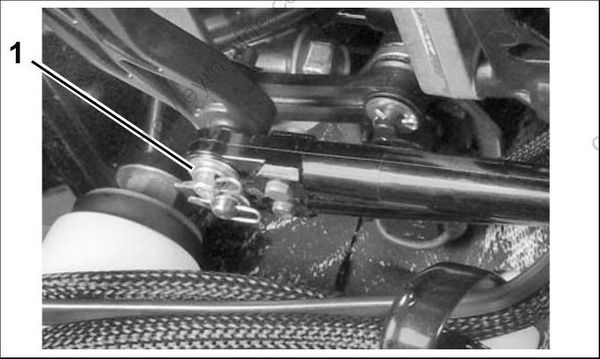
- Throttle cable retainer clip and washer
003967
Make sure that idle stop of the throttle lever is against the crankcase.
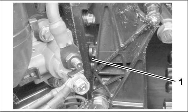
003968
Adjust the throttle cable trunnion to align with the trunnion block. Place the cable trunnion in the trunnion block.
IMPORTANT: Move control handle t o F OR WARD and pull back slowly to NEUTRAL. Make sure the engine throttle lever is against the stop. If not, remove slack by adjusting cable trunnion.
Install trunnion cover and screw. Tighten screw to a torque of 60 to 80 in. lbs. (7 to 9 N·m).
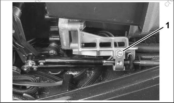
- Trunnion cover and screw, throttle cable
005039
Battery Cable Connections
Install battery cables on starter solenoid and main ground stud.
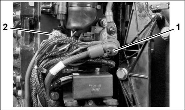
- Positive (+) battery connection
- Ground (–) connection
003975
System Check Harness Connections
Remove harness connector cover.
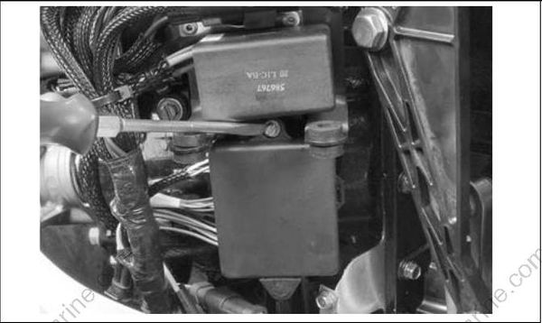
003972
Before installing electrical connectors, check that the seal is in place. Clean off any dirt from connectors. Apply a light coat of Electrical Grease_ to the seal only. DO NOT fill connectors with Electrical Grease.
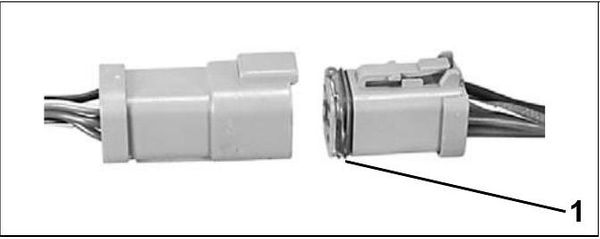
- Seal
42079A
Connect outboard main wire harness to boat wire harness. Secure connectors in bracket. Refer to the diagram inside of the electrical cover.
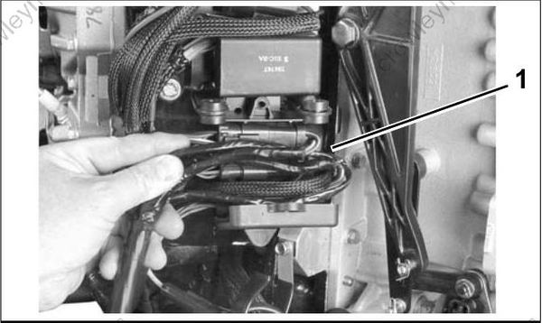
- Harness connections
003973
BE SURE all harness es and wires are not pinched, cannot contact flywheel, and do not interfere with moving throttle or shift linkages.
Replace harness connector cover.
I-Command Network Connections
If the outboard will be used with I-Command, or other NMEA 2000 compliant CAN bus instruments,
use the following connections to supply information to the network: If using an Evinrude ICON control system, the I Command Engine Interface Cable, Power Supply Kit, and Ignition and T rim Harness are not required. Connect the I-Command network directly to the ICON gateway module. Refer to the ICON Remote Control System Installation Guide If using a mechanical control system, connect the I-Command Engine Interface Cable to the EMM CAN bus connector.
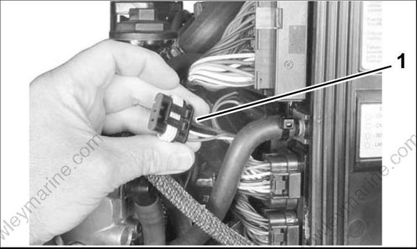
- EMM CAN bus connector
004265
Use an I-Command Ignition and Trim Harness to connect the outboard to the key switch and trim/tilt control. Sea l unused System Check connector with 6-Pin Connector Seal, P/N 586076.
If connecting to an existing I-Command Classic network, connect the purple wires bet ween the I Command Ignition and Trim Harness an d the I Command Engine Interface Cable. T his connection supplies power to the network when the key switch is on. I-Command Digital networks do not use this connection.
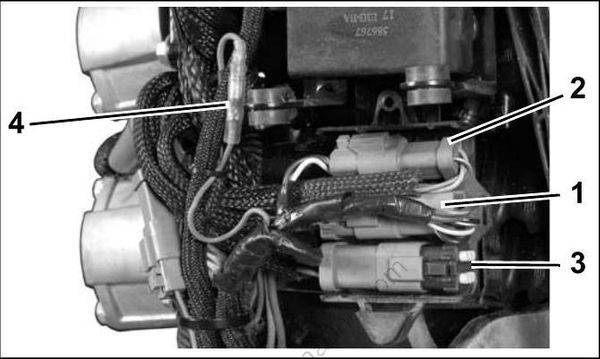
- I-Command Ignition connector
- Trim/Tilt connector
- System Check connector (with seal)
- Network power supply connector (Deutsch style networks)
006862
Route the harnesses around the starboard side of the power head along the same path as the battery cables. For an I-Command oil level display, an accessory CAN bus oil level sender must be installed in the oil tank. Connect the sender to the I-Command network. Refer to the I-Command Digital Network Guide. Use Evinrude Diagnostics software to adjust network settings in the EMM. From the Settings screen, select Engine Options.
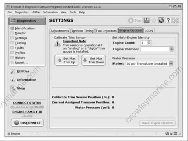
Engine Options Screen
008563
ICON Network Connections
If the outboard is equipped for an Evinrude ICON control system, connect the outboard to the network as follows. Refer to the ICON Rem ote Control System Installation Guide.Connect the buss cable from the rear network hub to the outboard’s network harness.
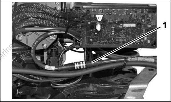
- ICON network connector
008001
IMPORTANT: Do not force connectors or locking rings. Properly aligned connectors assemble easily.
Do not use Electrical Grease on ICON buss cable connectors
To assemble the connectors:
- Use the large t abs and small t abs to carefully align buss cable connectors.
- Carefully align pins and socket s of connectors. Do NOT force connectors together.
- Tighten locking rings of buss connectors finger tight. Do NOT use locking rings to force connectors together.
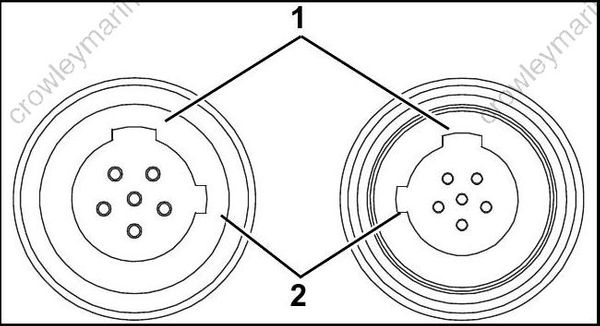
- Large tabs
- Small tabs
007883
Do not rot ate connectors until t hey align. This could result in a mismatched connection. It is possible for each pin to enter a socket even if the tabs are misaligned. Look at the t abs to en sure connector alignment prior to making the connection. Engine Monitor information is distributed to an ICON or I-Command network through the ICON gateway module. Refer to the I-Command Digital Network Guide. The ICON Harness an d Relay Kit, P/N 76529 6, must be used to provide power to boat accessories that require switched B+. This kit is used in place of connecting accessories to the “A” terminal o f the key switch. Accessories connected to the accessory power relay should not exceed 7 amps.
Do not connect boat accessories to the key switch of an ICON system. Connecting accessories to the key switch can ca use low
current, resulting in erratic operation of the remote control system. For more information, refer to t he ICON Remote Control System Installation Guide.
Water Pressure Gauge
To display engine water pressure, install a water pressure hose fitting in the cylinder block as shown. Use Pipe Sealant with Teflon on the threads of the hose fitting. Refer to installation instructions supplied with gauge. Route the water pressure hose around the starboard side of the power head along the same path as the battery cables.
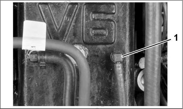
- Water pressure hose fitting
005035
For an I-Command water pressure display, several water pressure sensor kit s are available.
Refer to the Evinrude/Johnson Genuine Parts and Accessories catalog. To send water pressure data to the EMM, along with an I-Command display, install a water pressure transducer kit. Water pressure readings in excess of 40 psi (275 kpa) are possible for 90 ° V6 models at boat speeds in excess of 50 mph (80 kph/43 kts). Use 50 psi Water Pressure Transducer Kit, P/N 5008640.
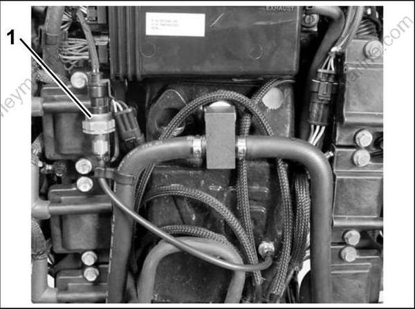
- Water pressure transducer
008131
Connect the transducer lead to the engine wiring harness connector.
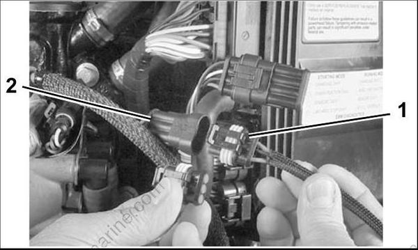
- Water pressure transducer lead
- Engine harness connector
004120
