PREPARE FOR WINTER: 10-50% discount on all OEM parts!

Unless prohibited by manufacturer. Does not include aftermarket or Crowley Marine branded products. Priced as marked.

Search Over 1 Million OEM Parts
Easy-to-use  parts diagrams Best price  guarantee Expert  live support 50+ years  of serving boaters Huge selection of OEM parts  -  from 1950 to 2026 Most parts in stock  -  Same day fulfillment
Most parts in stock- Same day fulfillment

Service Manual 5008740_200-300 HP 90 ° V Oiling System [Oiling System Circuit Diagram]

Related Products:
Service Manual 5008740_200-300 HP 90 ° V Oiling System [Oiling System Circuit Diagram]
5008740
BRP Marine

OILING SYSTEM CIRCUIT DIAGRAM
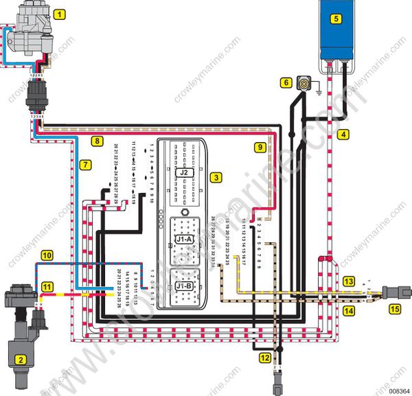
  1. Crankcase Oil Injection Pump
  2. Cylinder Oil Injection Pump
  3. EMM
  4. 55 V Circuit (WHITE/RED)
  5. Capacitor
  6. Grounds, NEG (BLACK)
  7. EMM to Oil Solenoid (BLUE)
  8. Oil Pressure Sensor, +5 V analog (RED)
  9. Oil Pressure Sensor Signal (TAN/WHITE)
  10. Rear Oil Injector control (BLUE/RED)
  11. Rear Oil Injector +12 V (RED/YELLOW)
  12. Low Oil Switch (TAN/BLACK)
  13. NO OIL Signal (TAN/YELLOW)
  14. LOW OIL Signal (TAN/BLACK)
  15. SystemCheck Connector
Share on social:

Related Products