

GEARCASE ASSEMBLY
Water Intake Screens
Install water intake screens. Tighten screws to a torque of 60 to 84 in. lbs. (7 to 9.5 N•m).
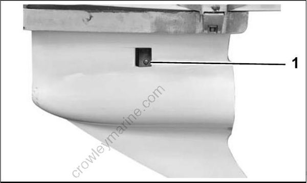
- Water intake screen
Shift Housing, Gear, and Propeller Shaft Installation
Push shifter detent into farthest downward position. Tip the rear of the gearcase slightly down ward to assist in the installation of the shaft assembly.
Be sure the thrust bearing and the thrust washer are in the proper position. Insert the shaft assembly fully into the gearcase while aligning shift housing pin with hole in forward end of gearcase housing.
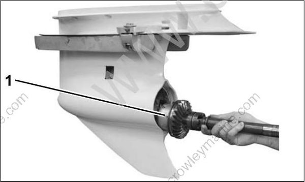
- Pin
Shift Rod Housing Installation
Lubricate a new shift rod cover O-ring with Triple- Guard grease. Install the O-ring into the shift rod cover.
IMPORTANT: Make sure O-ring is fully seated in groove.
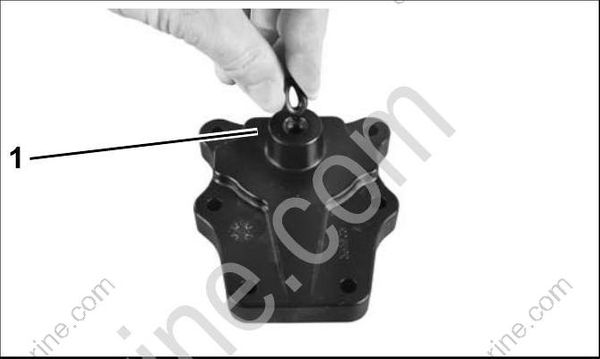
- O-ring
Install the shift rod spacer on the shift rod (25 in. models). On 30 in. models, inst all the extension (not shown).
Place the shift rod grommet on the shift rod.
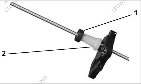
- Grommet
- Shift rod spacer
Apply Triple-Guard grease to the threaded end of the shift rod and insert it through the cover. Turn the shift rod while pushing it through the cover to avoid damaging the O-ring.
“L2” TYPE GEARCASES
Apply Gasket Sealing Compound to both sides of a new shift rod cover gasket. Place the gasket on the gearcase.
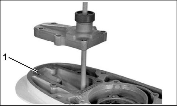
- Cover gasket
“M2” Type Gearcases
Apply Adhesive 847 to seal groove of shift rod cover. Place a new shift rod cover seal in groove.
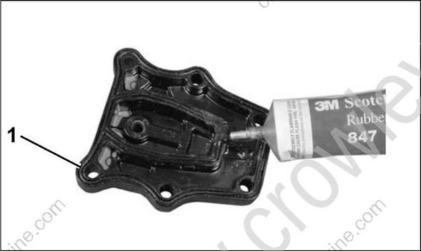
- Cover seal
ALL GEARCASES
Thread the shift rod into the shifter detent about four turns.
Move shift rod from side to side while pushing on the propeller shaft to ensure proper alignment of the bearing housing locator pin into the pin hole in the gearcase.
Apply Gasket Sealing Compound to the threads of the shift rod cover screws. Tighten the screws to a torque of 60 to 84 in. lbs. (7 to 9.5 N•m).
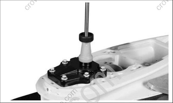
Refer to SHIFT ROD ADJUSTMENT on p. 295.
Pinion Gear and Driveshaft Installation
Refer to DRIVESHAFT SHIMMING on p. 310.
Install new seals in driveshaft bearing housing. Refer to Driveshaft Bearing Housing Service on p. 307.
Place the driveshaft thrust bearing, thrust washer, and correct shim(s) on the driveshaft as shown.
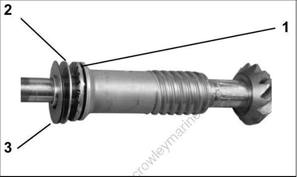
- Thrust bearing
- Thrust washer
- Shim(s)
Using Driveshaft Seal Protector , P/N 318674, slide the driveshaft bearing ho using onto the driveshaft and into position in the gearcase.
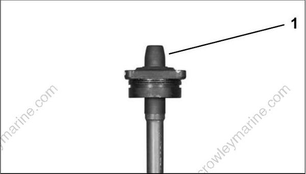
- Seal protector
Adjust shift rod to move clutch dog as far forward as possible. Be sure excess grease is removed from the pinion bearing.
Washer must be snapped into recess of pinion gear.
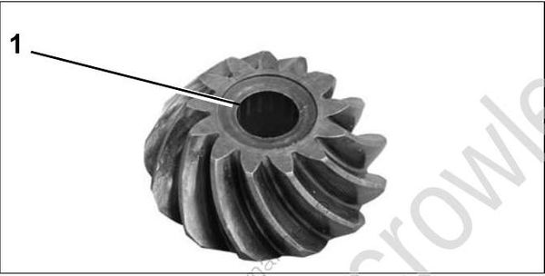
- Washer
IMPORTANT: The inside taper of the pinion gear and the driveshaft taper MUST be completely free of grease. Clean the tapers with Cleaning Solvent. Use a shop towel free of grease and lint.
Place the pinion gear into the gearcase. Insert the driveshaft into the gearcase and through the pin ion gear.
Lightly coat the threads of a new pinion nut with outboard lubricant. Use Pinion Nut Starting Tool, P/N 342216, to install nut on the driveshaft. Turn the driveshaft by hand to thread the nut on to shaft.
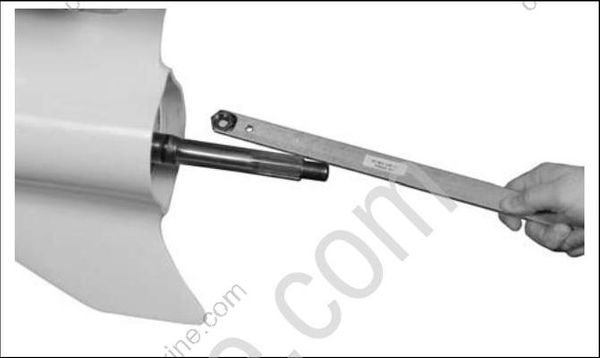
Apply Gasket Sealing Compound to the threads of the driveshaft bearing housing screws. Tighten screws in stages to a torque of 120 to 144 in. lbs. (13.5 to 16.5 N•m).
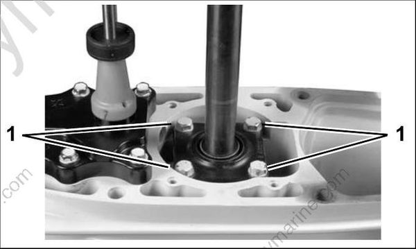
- Driveshaft bearing housing screws
Use Driveshaft Holding Socket, P/N 311875, Pin ion Nut Holder, P/N 334455, and Wrench Retainer, P/N 341438, to tighten the pinion nut to a torque of 100 to 110 ft. lbs. (136 to 149 N•m).
Pad handle of holder to prevent damage to gear case.
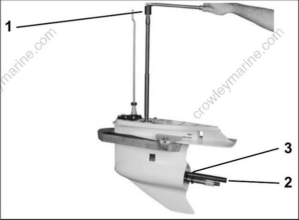
- Holding socket
- Pinion holder
- Retainer
Propeller Shaft Bearing Housing and Gear Installation – “L2” Type
IMPORTANT: The propeller shaft bearing housing on the “L2” type gearcases is PRESSED into the gearcase housing.
Oil and install thrust bearing and thrust washer on hub of reverse gear.
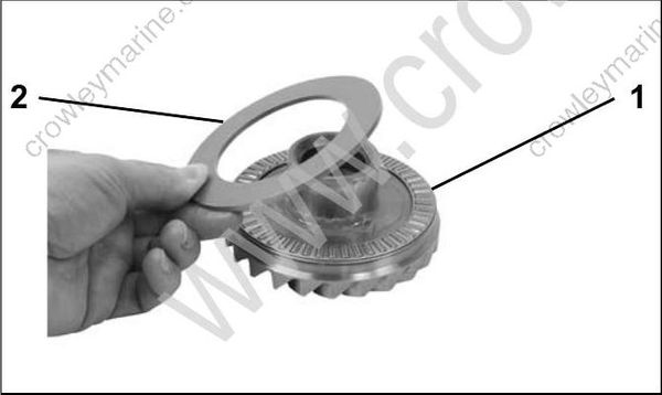
- Thrust bearing
- Thrust washer
Slide the gear assembly onto the propeller shaft until it engages the pinion gear.
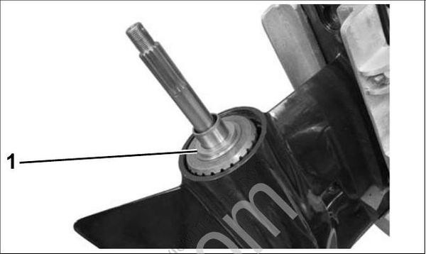
- Thrust bearing and thrust washer
Lightly apply Triple Guard Grease to a new bearing housing O-ring. Install O-ring in groove in the housing. Grease the machined side surfaces of bearing housing.
Install housing into gearcase. Align screw holes with retainer slots in gearcase.
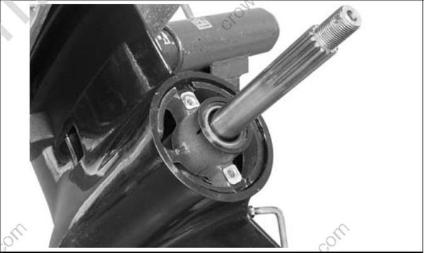
Use Installer Handle, P/N 345822, Propeller Shaft Bearing Housing Installer, P/N 354058, Gearcase Fixture, P/N 354059 and an appropriate floor press (10 ton or greater) to install housing into gearcase. Align and level gearcase assembly in fixture as shown. Secure fixture to floor press.
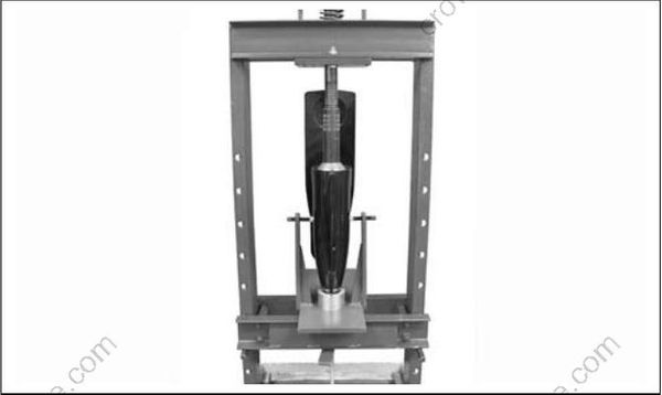
Housing must be completely seated in gearcase to install retainer tabs. Depth to retainer tab surface on bearing housing is approximately 1 in. (25.4 mm).
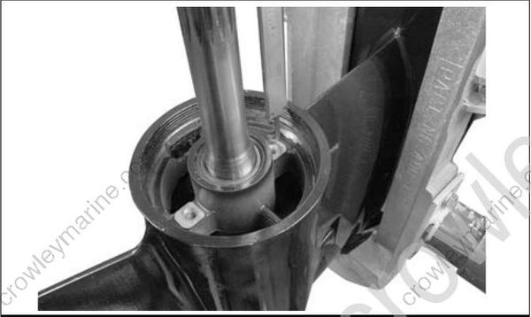
Install two retainers, washers and screws. Apply Ultra Lock to threads and tighten screws to a torque of 18 to 20 ft. lbs. (24 to 27 N•m).
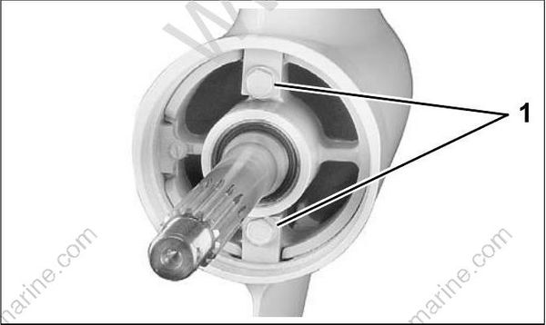
- Retainer tab screws
Propeller Shaft Bearing Housing and Gear Installation – “M2” Type
IMPORTANT: The propeller shaft bearing housing on the “M2” type gear cases is PRESSED into the gearcase housing.
Oil and install thrust bearing and thrust washer on hub of reverse gear. Slide the gear assembly onto the propeller shaft until it engages the pinion gear.
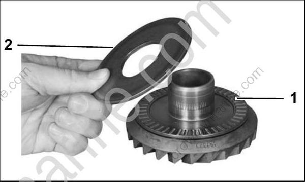
- Thrust bearing
- Thrust washer
Lightly apply Triple Guard Grease to new bearing housing O-rings. Install O-rings in grooves in the housing. Grease the machined side surfaces o f bearing housing.
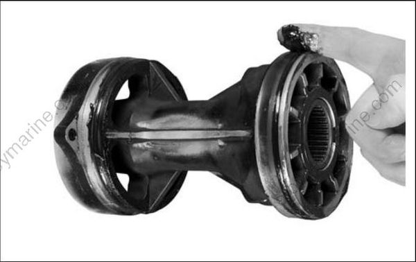
Place bearing housing in gearcase.
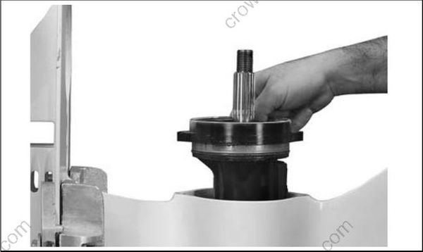
Align retaining holes in bearing housing with screw holes in gearcase . Thread Alignment Pins, P/N 354140, into gearcase.
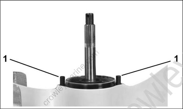
- Alignment pins
Use Installer Handle, P/N 345822, Propeller Shaft Bearing Housing Installer, P/N 354057, Gearcase Fixture, P/N 354059 and an appropriate floor press (10 ton or greater) to install housing into gearcase. Align and level gearcase assembly in fixture as shown. Secure fixture to floor press.
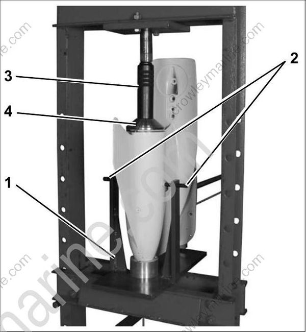
- Gearcase fixture, P/N 354059
- Vertical alignment screws
- Handle P/N 345822
- Housing installer P/N 354057
Housing must be completely seated in gearcase to inst all retainer screws. Bearing housing is approximately level with gearcase.
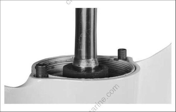
Apply Ultra Lock to threads and inst all two retaining screws. Tighten screws to a torque of 18 to 20 ft. lbs. (24 to 27 N•m).
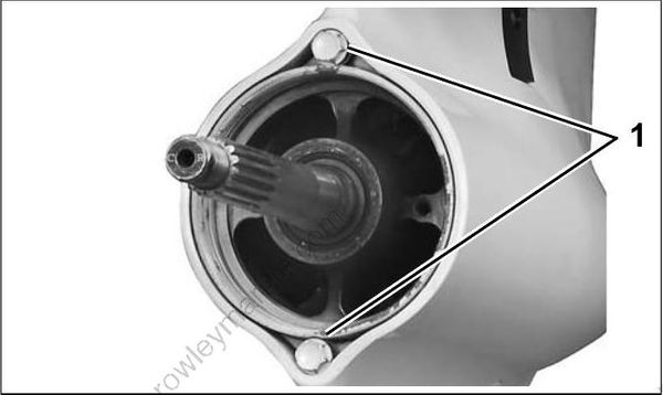
- Retainer screws
Final Assembly and Adjustment
To complete gearcase assembly, refer to:
- GEARCASE LEAK TEST on p. 288
- WATER PUMP SERVICE on p. 292
- SHIFT ROD ADJUSTMENT on p. 295
- GEARCASE REMOVAL AND INSTALLATION on p. 289
- Gearcase Lubricant on p. 37
- Propeller Hardware Installation on p. 287
- Trim Tab Adjustment on p. 30.
During break-in period of are assembled gear case, change the gearcase lubricant between 10 to 20 hours of operation.
