

12 V Charging Circuit
To test the operation of the regulator in the EMM, you must be able to run the outboard continuously at approximately 5000 RPM, such as in a test tank or on a marine dynamometer.
The test consist s of monito ring the system’ s response to a partially discharged battery. Use a variable load tester to discharge the battery.
IMPORTANT: The regulator requires voltage to operate. Before proceeding, make sure there is at least 7 V on t he positive terminal of the starter solenoid.
Disconnect the battery cables at the battery.
Use an inductive amp meter or connect a 0 to 50 A ammeter in series between the red wire(s) of engine wire harness (alternator output from EMM) and the positive (B+) battery cable terminal of starter solenoid.
IMPORTANT: This outboard has dual out put charging. Each output is isolated and regulated. Each output is 25 A. Combined output is approximately 50 A. Refer to engine wiring diagram.
Fluke model 334 or 336, Snap-On model MT110 or EETA501, and various other amp meters should be available through local tool suppliers. Reconnect the battery cables.
Following the manufacturer’s directions, connect the variable lo ad tester (carbon pile) across the battery terminals. Stevens model LB-85 and Snap-On model MT540D are examples o f testers available.
Excessive battery discharge rates might overheat battery causing electrolyte gassing. This might create an explosive atmosphere. Always work in a well ventilated area.
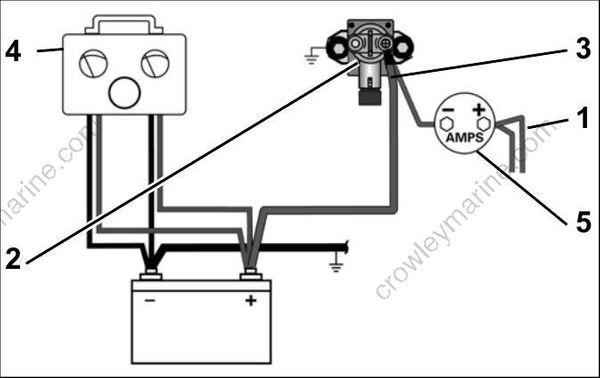
Variable Load Test Diagram
- Red wires (alternator output from EMM)
- Starter solenoid
- Battery cable terminal (B+)
- Variable load tester
- Ammeter
Start and run the outboard at approximately 3500 RPM. Use the variable load tester to draw the battery down at a rate equivalent to the stator’s full output.
The ammeter should indicate nearly full output, approximately 50 A (or 25 A for each output) between 2000 and 4000 RPM.
Above 4000 RPM, charging output is reduced to 40 A.
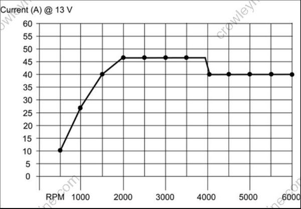
Battery Charging Graph
Decrease the battery load toward 0 A.
Ammeter should show a reduced output. As the current draw decreases, the battery voltage should stabilize at approximately 14.5 V.
If results vary, check stator BEFORE replacing the EMM. See STATOR TESTS on p. 96.
Auxiliary Battery Charge Wire
The auxiliary battery charge feature requires auxiliary battery charge kit, P/N 500625 3 (or equivalent).
IMPORTANT: Disconnect all accessories from the auxiliary battery. Auxiliary battery must read a minimum of 8.5 V at the beginning of these tests and remain connected to the outboard during the tests.
Check battery ground cable for continuity.
With the key switch OFF, check battery voltage at auxiliary battery , then check voltage at auxiliary battery connection. If the rea dings are no t the same, replace wire to auxiliary battery. The auxiliary battery wire must be at least 10-gauge and it must be protected by a 50 A fuse or circuit breaker at the battery.
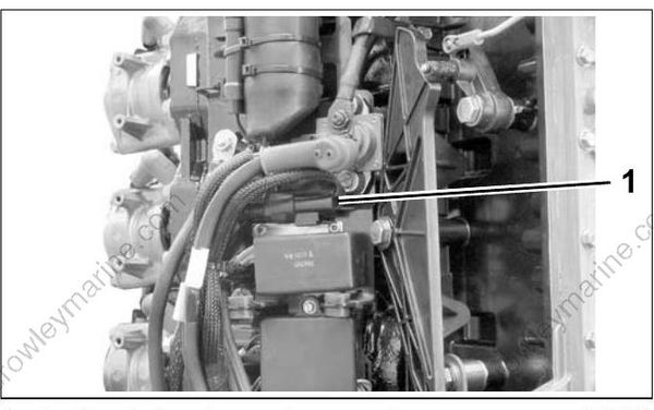
- Auxiliary battery charge wire connection
With outboard running at 1000 RPM, voltage must read higher than with key OFF and increase steadily to approximately 14.5 V as the outboard RPM increases.
If there is no increase, turn the key switch to OFF and test red/black wire between the EMM an d auxiliary battery connection.
Continuity indicates faulty output from EMM. Check 12 V alternator output before replacing EMM for faulty auxiliary battery, charge isolator circuit.
No continuity indicates faulty wiring.
55 V Alternator Circuit
Check battery ground cable for continuity.
With the key switch ON, check battery voltage at battery (12 V).
Then, use Electrical Test Probe Kit, P/N 342677, and a digital multimeter set to read 55 VDC to check voltage on white/red wires at J2 connector of EMM. Voltage at EMM connector should be approximately 30 V.
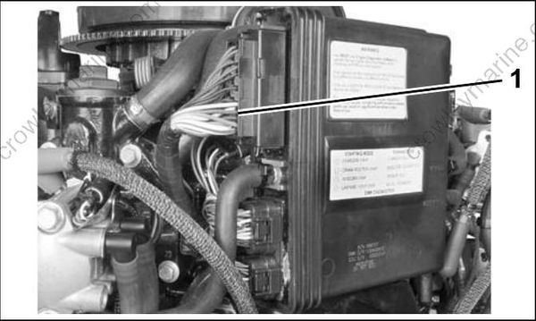
- J2 connector of EMM
With outboard running at 1 000 RPM, voltage on white/red wires should increase to 55 V . Voltage readings at a specific speed (RPM) should be steady.
If there is any other reading, refer to STATOR TESTS on p. 96. Inspect the stator wiring a nd connections. Inspect the capacitor wiring, connections, and capacitor. Repair the wiring or replace a faulty capacitor, stator, or EMM.
