

Disassembly
Thoroughly clean the unit before disassembling. Scrub all outside surfaces with a stiff brush and hot, soapy water to prevent surface dirt from contaminating internal parts.
Always use a lint free shop cloth when handling power trim/tilt components.
If painting the unit is required, paint it after it is completely assembled. Painting of individual components may cause flakes of paint to enter the hydraulic passages during assembly. Tape the trim/tilt piston rods before painting.
There may be high pressure behind some power trim valves. To avoid injury when removing manual release valve, be sure to cover valve with a shop cloth until the pressure is released. Wear safety glasses.
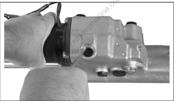
IMPORTANT: Before removing manual release valve, relieve pressure by fully extending cylinder. Screw the manual release valve in. Remove the retaining ring using a small pick or screwdriver. Discard the retaining ring.
004279
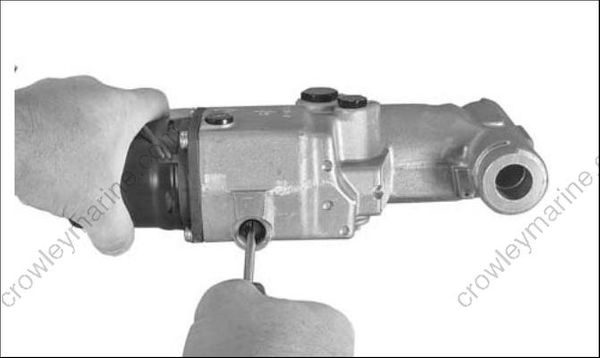
Slowly remove the manual release valve. There may be pressure behind the valve—wear safety glasses.
004285
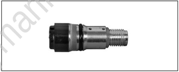
Inspect the manual release valve. Discard the O-rings on the housing.
007108
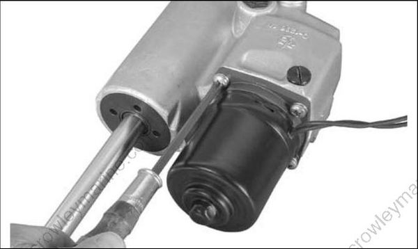
Remove the four large motor flange retaining screws. Remove the motor and discard O-ring, screws, and washers.
004282
Remove drive coupler from either the motor or the pump assembly.
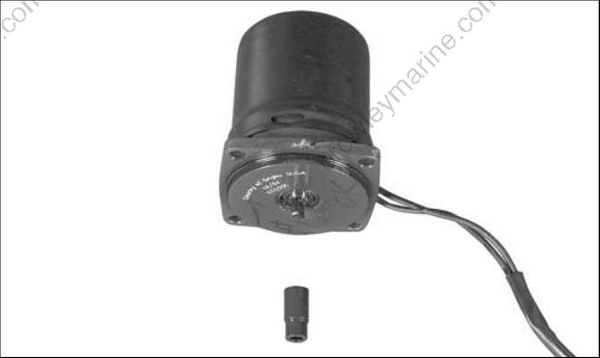
004281
Assembly
IMPORTANT: Use only Evinrude/Johnson Bio degradable TNT Fluid to fill the hydraulic system.
Install drive coupler in pump assembly.
Install a new motor O-ring.
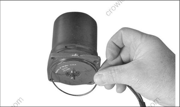
004280
Position the motor on the manifold and install four new screws and lock washers. Tighten the screws 35 to 50 in. lbs. (4 to 5.6 N·m).
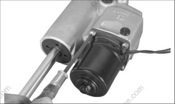
004282
Oil O-rings and install them on the manual release valve. Oil and install the manual release valve. Tighten the valve to a torque of 45 to 55 in. lbs. (5.1 to 6.2 N·m).
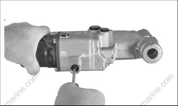
004285
Install new retaining ring in groove.
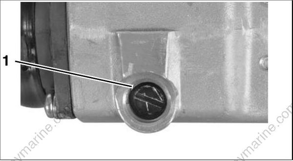
004283
- Retaining ring
Fill the oil reservoir up to the fill plug with Evinrude/Johnson Biodegradable TNT Fluid. Install the fill plug.
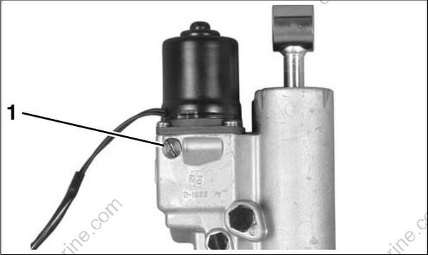
004278
- Reservoir cap
Run the motor, then recheck oil level. Cycle the unit several times and check the oil level when the cylinder is fully extended. Oil should be level with bottom of fill port. Install and tighten the fill plug to a torque of 45 to 55 in. lbs. (5 to 6 N·m).
SERVICING – THREE PISTON SYSTEM
Disassembly
Before removing the manual release valve, operate the unit to the full UP position, then run the unit down momentarily and loosen the reservoir cap one full turn.
To avoid personal injury, always wear eye protection when servicing the hydraulic unit. Since there might be significant residual pressure behind some components, cover each component with a shop cloth as you remove it.
Thoroughly clean the unit before disassembling. Scrub all outside surfaces with a stiff brush and hot, soapy water to prevent surface dirt from contaminating internal parts.
Do not apply heat to the cylinder body or cylinders. Excessive heat can cause high pressure leaks or failure of parts.
Always use a lint free shop cloth when handling power trim/tilt components.
If painting the unit is required, paint it after it is completely assembled. Painting of individual components may cause flakes of paint to enter the hydraulic passages during assembly. Tape the trim/tilt piston rods before painting.
