

TPS Calibration
Use Evinrude Diagnostics software to tell the EMM what throttle position sensor voltage is when the throttle plates begin to open.
Set TPS Calibration after replacing or adjusting any throttle body or throttle linkage parts.
Remove the air silencer.
Do NOT start the outboard.
On the Settings/Adjustments screen of the diagnostics software, click the “Set TPS Calibration” button.
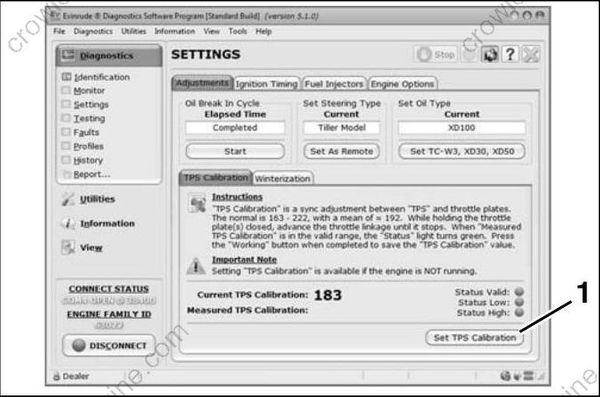
- TPS Calibration button
While holding the throttle plates closed, advance the throttle linkage until it stops. The “Measured TPS Calibration” field on the screen will increase.
Click the “Working” button in the software to calibrate the TPS.
Install the air silencer.
ELECTRIC STARTER SERVICING
Starter Removal
IMPORTANT: Do not clean the starter drive while the starter motor and drive are installed on the powerhead. The cleaning agent could drain
into the starter motor, washing dirt from the drive into the starter bearings and commutator.
Disconnect the battery cables at the battery.
Remove the starter positive (+) cable from post on starter.
Remove the four frame and bracket mounting screws. Remove the starter.
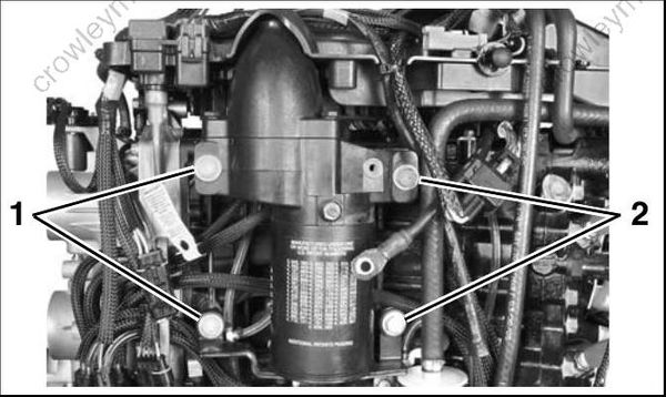
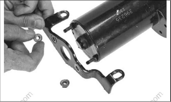
Loosen the two nuts used to fasten the starter bracket. Remove the nuts and bracket.
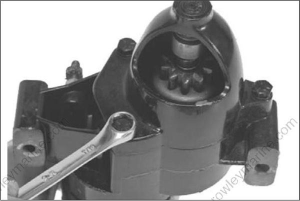
Remove the screws, lock washers, and pinion housing.
Starter Disassembly
Lift and remove the wave washer and bushing.
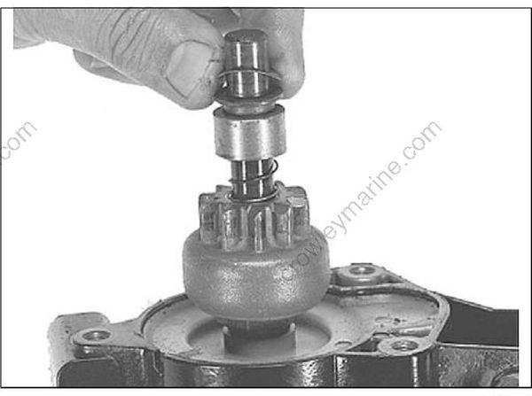
Place an appropriate-sized deep socket on the spacer.
Hit the socket with a mallet to lower the spacer and expose the retaining ring under the spacer.
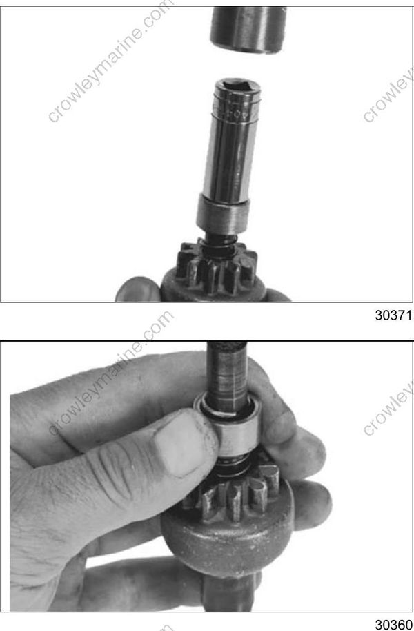
Remove the retaining ring, spacer, and spring from pinion shaft.
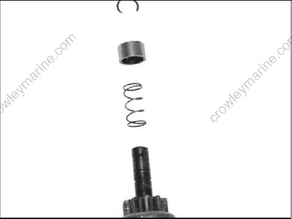
Remove pinion and plastic weather cover from pinion shaft.
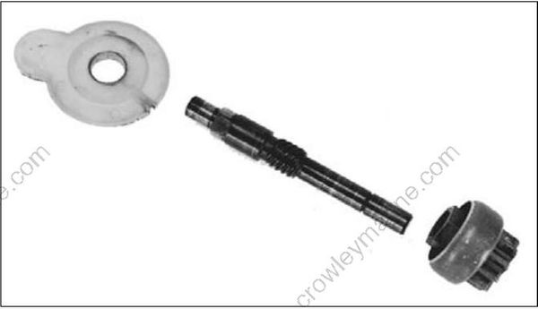
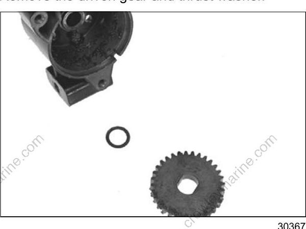
Remove the driven gear and thrust washer.
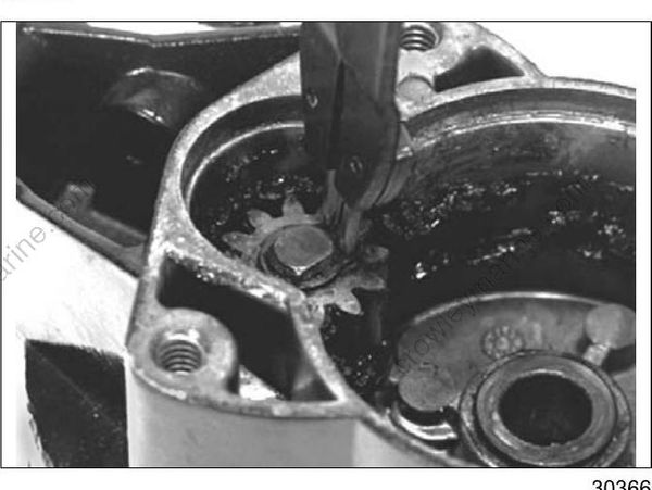
Using No. 2 external retaining ring pliers, remove the retaining ring and drive gear from the armature shaft.
Remove the two thru-bolts. Mark the end cap orientation, and remove the cap.
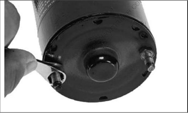
Gently tap the starter frame with a rubber mallet to loosen it.
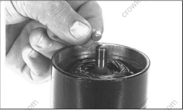
Find the insulator cap (end of the shaft or inside the end cap). Inspect and replace, if necessary.
Note the alignment marks by the positive terminal stud. Hold the armature in place, and slide the frame away from the gear housing.
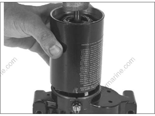
Slowly remove the armature and thrust washer. Do not lose the brush springs.
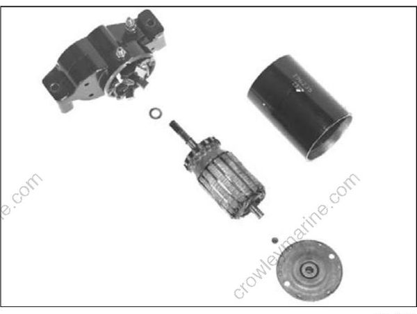
Starter Cleaning and Inspection
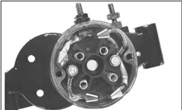
Inspect the brushes for wear and damage. Replace brushes if damaged or worn. Replace weak brush springs.
Inspect and replace locating ring on armature shaft, if necessary.
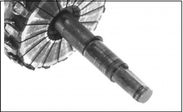
Clean the commutator with 300-grade emery cloth. If commutator surface is unevenly worn or pitted, turn it on a lathe. Remove any trace of oil or metal dust from the commutator.
Check the armature on a growler for shorted turns using a test light or meter. Inspect armature insulation for indications of overheating or damaged windings. Clean off any carbon deposits or foreign matter which could contribute to failure of windings.
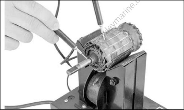
TYPICAL
Check permanent magnets. Make sure they strong attract any steel or iron object held inside frame. Weak magnetism could cause excessive
RPM on No Load Current Draw Test on p. 101.
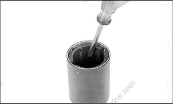
TYPICAL
After disassembling the drive, clean each part with Cleaning Solvent and inspect for wear and distortion.
If the pinion does not properly engage the flywheel, the pinion and screw shaft assembly could be worn, distorted, or dirty. Locate the cause of binding and correct it before completing the assembly.
Inspect and replace end cap thrust washer if distorted or worn excessively.
Inspect and replace armature shaft snap ring if worn or distorted.
Starter Assembly
IMPORTANT: If removed, apply Locquic Primer and Screw Lock to the brush card screws before installing.
Route the brush leads and install the springs and brushes. Compress the spring with a modified putty knife.
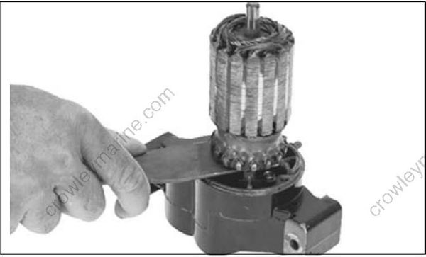
IMPORTANT: Incorrect orientation of the brushes could damage the starter or cause reverse rotation.
Apply Moly Lube to the armature bushing. Install the thrust washer and armature.
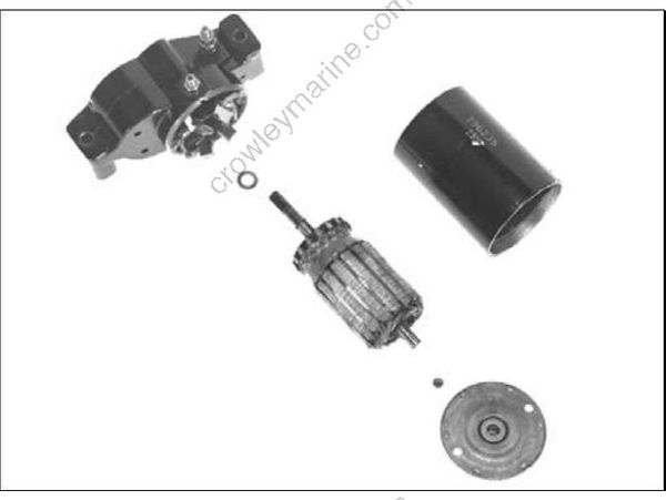
Align the starter frame and make sure the long alignment mark matches the mark next to the positive terminal stud on the gear housing.
Push the armature down firmly and slide the frame into place. Align the notches in the gear housing and frame.
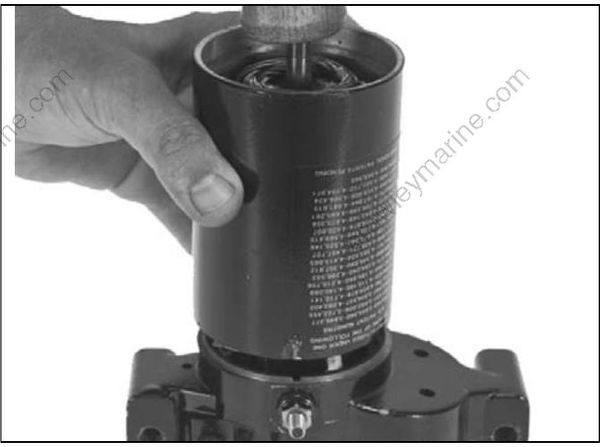
Install insulator cap on end of shaft.
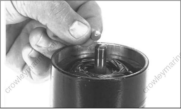
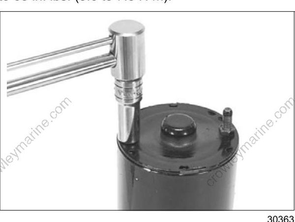
Apply a light coat of Moly Lube to the end cap bearing, and install the end cap. Install the two thru-bolts. Tighten to a torque of 50
to 65 in. lbs. (5.6 to 7.3 N·m).
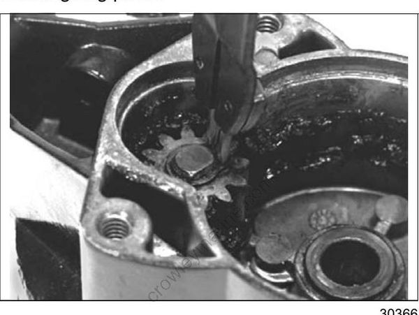
Lightly coat the drive gear with Triple-Guard grease, and install it on the armature shaft. Install the retaining ring (flat side up) with No. 2 external retaining ring pliers.
Lightly coat the gear housing bearing with Moly Lube. Lightly coat the driven gear with Triple Guard grease. Install the thrust washer and driven gear.
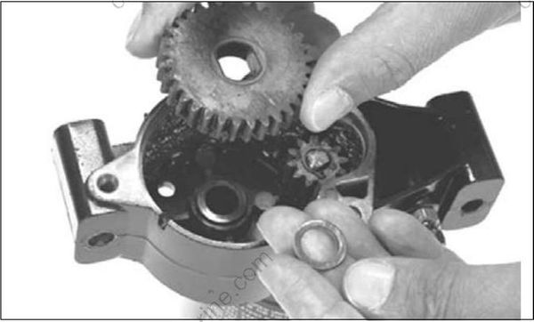
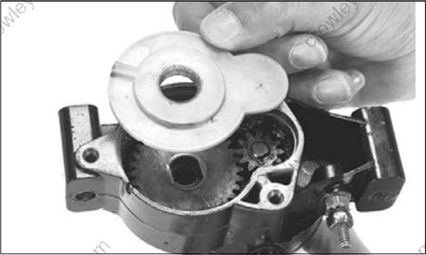
Install the weather cover.
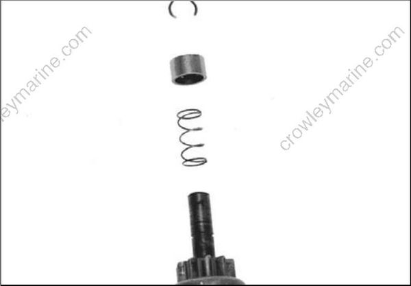
If removed, install the spring and spacer (large diameter up) on the pinion shaft. Secure with retaining ring. Install bushing and wave washer (convex side down).
Lightly coat the pinion shaft splines (helix) with Starter Bendix Lube. Lower the pinion into place without displacing the driven gear or thrust washer.
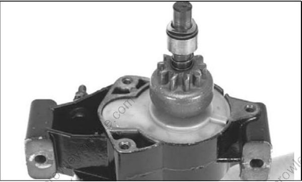
Lightly coat the pinion housing bearing with Starter Bendix Lube, and install the pinion housing screws and lock washers. Tighten the screws to a torque of 60 to 84 in. lbs. (7 to 9.5 N·m).
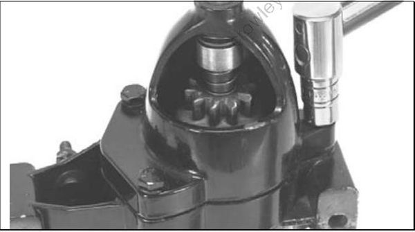
Install the bracket. Apply Nut Lock to the thrubolts. Install the nuts and tighten to a torque of 50 to 65 in. lbs. (5.6 to 7.3 N·m).
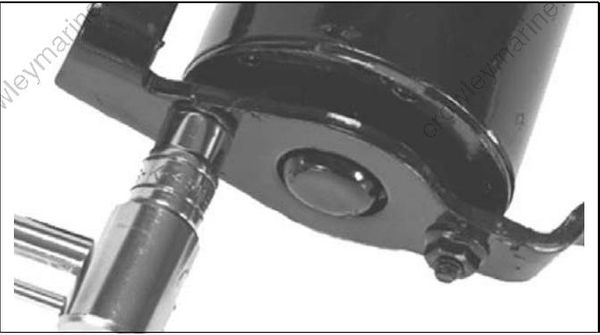
To test the assembly and operation of the starter, refer to No Load Current Draw Test on p. 101.
Starter Installation
Apply Locquic Primer and Nut Lock to the threads of the four starter mounting screws. Position the starter and install the screws and lock washers.
First, tighten the top two screws, then the bottom two screws, to a torque of 168 to 192 in. lbs. (19.0 to 21.5 N·m).
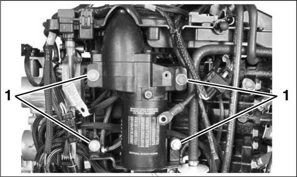
- Screws
Attach starter positive (+) cable to post with lock washer and nut; tighten securely. Coat connections with Black Neoprene Dip.
CONNECTOR SERVICING
DEUTSCH Connectors
IMPORTANT: Electrical Grease is recommended. Incorrect grease application can cause electrical or warning system problems.
To disconnect the connector, press the latch and pull the connectors apart.
To connect the connector, confirm that the seal is in place. Clean off any old grease and dirt from connectors. Apply a light coat of Electrical Grease to seal only. Push connectors together until
latched.
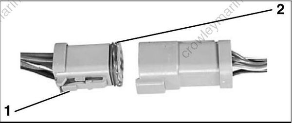
- Latch
- Seal
Terminal Removal
Use hook-end of Connector Service Tool, P/N 342667, to pull out wedge from receptacle, or use other end of tool to pry out wedge from plug.
Use needle-nose pliers to remove wedge from 3-pin receptacle.
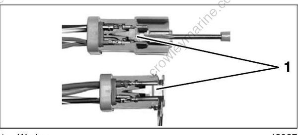
- Wedge
