

Hull Preparation
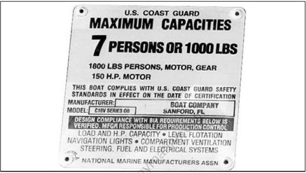
Maximum Capacity
Do not overpower the boat by installing an outboard that exceeds the horsepower indicated on the boat’s capacity plate. Overpowering could result in loss of control.
Before installing outboard:
- Refer to the boat manufacturer's certification label for maximum horsepower rating.
- Refer to ABYC Standards to determine the maximum horsepower capacity for boats without certification labeling.
1029A
Mounting Surface
Inspect transom surface befo re mou nting outboard.
- The transom should meet ABYC Standards.
- The transom must be flat and cannot have any protrusions.
- The transom angle should be approximately 14 degrees.
- Check transom strength and height.
The stern brackets must contact the flat surface of the transom. Modify trim that prevents the stern brackets from resting against the transom surface. Do not modify stern brackets.
DO NOT install an outboard on a curved or irregular surface. Doing so can wear, bind, and damage components, causing loss of control.
Transom Clearances
Make sure the transom and splash well area provide adequate clearances.
- The top edge of the transom should be wide enough to allow full steering travel. The ABYC standard for most single outboard installations is 33 in. (84 cm).
- Check cable and hose routing clearances.
- Make sure there is clearance for mounting bolts and washers. Check the inside area of the transom for obstructions prior to drilling holes.
Water Flow
Inspect the hull area directly in front of the mounting location.
Boat-mounted equipment should not create turbulence in the water flow directly in front of the outboard's gearcase. Turbulence or disruptions in the water flow directly in front of the gearcase will affect engine cooling and propeller/impeller performance.
Avoid locating outboard centerlines within 3 in. (76 mm) of bottom strakes on dual-outboard installations.
Transom Brackets and Jack Plates
When mounting an outboard on a jack plate:
Refer to the manufacturer's recommendations for maximum weight and horsepower.
The jack plate must pro vide a rigid, one -piece mounting assembly—either a solid surface, or surfaces adequately connected to prevent flexing or twisting.
DO NOT use a jack plate constructed in two separate pieces—lack of support can twist the stern brackets, wear tilt tube bushings and thrust rollers, and bend or break components.
IMPORTANT: Damage caused by use of a two piece jack plate or unstable mounting surface will not be covered by warranty.
Recommended Designs
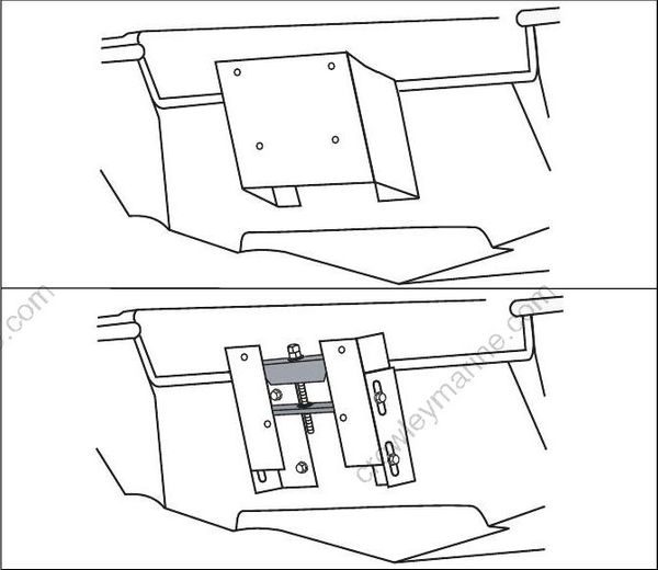
007992 007991
Not Recommended
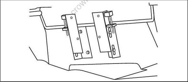
DR5703
Whenever possible, use mounting hardware supplied with the outboard to install jack plate on transom. Tighten to a torque of 40 ft. lbs. (54 N·m).
To prevent damage to outboard, check installation frequently for:
• Loose mounting bolts and nuts
• Loose tilt tube or steering cable nuts
• Elongated mounting holes
• Bent or deformed washers
Replace any hardware that fails to maintain torque specifications.
Mounting Hardware
Use all mounting hardware supplied with the outboard to help ensure a secure installation. Substituting inferior hardware can result in loss of control.
Outboard mounting hardware must meet minimum specifications for material and strength.
Outboard mounting bolt s, backing plate s, washers, and nuts are used to attach the outboard to the shipping pallet. If alternate bolt lengths or replacement p arts are required, u se only Evinrude/Johnson Genuine Parts.
IMPORTANT: Standard screws offered by local merchants may not provide the high strength
required for outboard installations.
Transom Measuring and Drilling
Hull Centerline
Use the chines of the boat as reference points to locate the centerline of the boat transom.
Use a straightedge to draw a line connecting the port and starboard chines.
Use a framing square to accurately place a vertical line on the transom. The centerline of the hull should be in line with the keel, and perpendicular to the midpoint of the line connecting the chines.
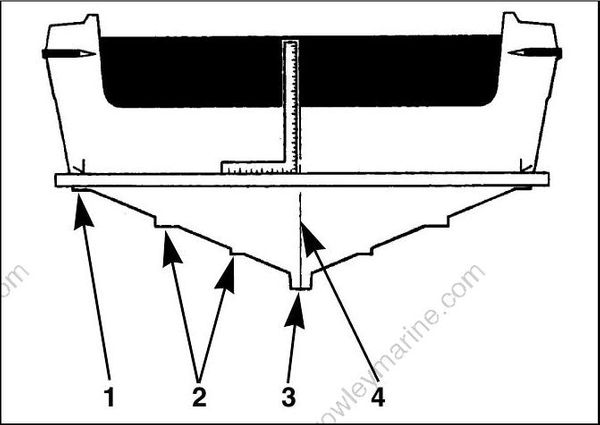
DR5568
- Chine
- Strake
- Keel
- Hull centerline
Transom Height
Make sure the transom height matches the length of the outboard to be installed.
- A 19 to 21 in. (48.3 to 53.3 cm) transom height uses a 20 in. (50.8 cm) shaft outboard.
- The shaft length of the outboard being installed should come close to matching the transom height of the boat.
Determine transom height by measuring from the top edge of the transom, along the centerline.
Use a straightedge as a reference to extend the bottom of the boat.
Position the straightedge a long centerline. The distance from the top edge of the straightedge to the top edge of the transom is the actual transom height.
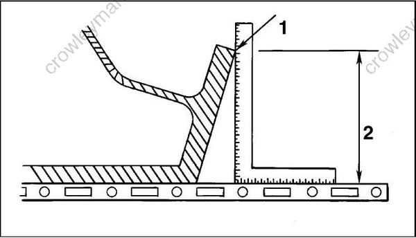
DR5541
- Top edge of transom
- Actual transom height
Transom Drilling Locations
Center the outboard on the transom (or mounting bracket) and tighten clamp screws by hand.
Use each stern bracket’s mounting ho les as a guide to drill four 11/32 in. (8.7 mm) holes through the transom.
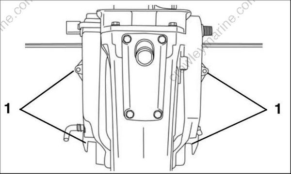
Drilling Diagram
IMPORTANT: This is not a template.
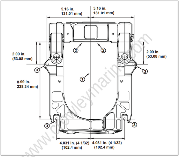
- Center of Transom
- Top of Transom
- 5/16” Bolt Hole Locations
IMPORTANT: This is not a template.
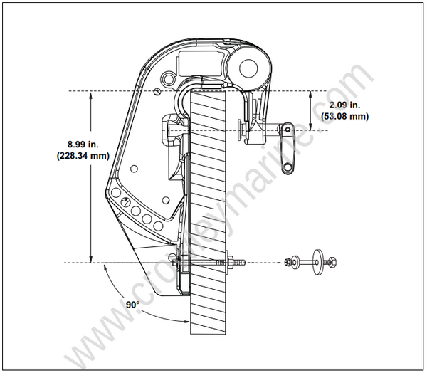
Lifting the Outboard
Lifting Fixtures
To avoid personal injury, make sure the lifting capacity of the hoist is at least twice the weight of the outboard.
DO NOT allow the lift hook or chain from the hoist to come in contact with any part of the engine during lifting.
Use correct Lifting Fixture to lift outboard:
| Model | Lifting Fixture |
|---|---|
| MFE 55 | P/N 396748 with 1 1/8 in. screws |
With recoil starter removed, pla ce lif ting tool on flywheel and se at the three screws completely. Refer to RECOIL STARTER REMOVAL on p. 265.
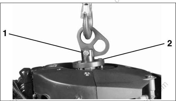
002098
- Lifting fixture
- 1 1/8 in. screws
Use only the 1 1/8 in. (short) screws, P/N 398067, included with the tool to avoid damage to electronic components under the flywheel.
Fasten appropriate chain hook to eye of tool. Carefully hoist outboard with chain.
Outboard Mounting
Mounting Height
Boat performance depends on outboard mounting height.
Generally, the anti-ventilation plate of the gearcase should align with the bottom of the hull. Conventional V-hulls often perform well with the anti ventilation plate approximately 1 in. (25 mm) above the bottom of the hull.
Boats that exceed 50 MPH ma y benefit from higher outboard heights. Consult the boat manufacturer for specific outboard mounting height information for a particular hull.
Test outboard and boat performance at different heights until the best performance is achieved.
Be sure that outboard water pressure is not adversely affected by the mounting height of the outboard.
Mounting Bolt Installation
IMPORTANT: Use a marine sealant rated for above or below waterline use. RTV silicone is not approved for below waterline use. Polyurethane sealants are not easily removed and may damage outboard or boat mounting surfaces.
Apply marine sealer under h ex heads of bolts, on the mounting plates, and to the bolt shanks.
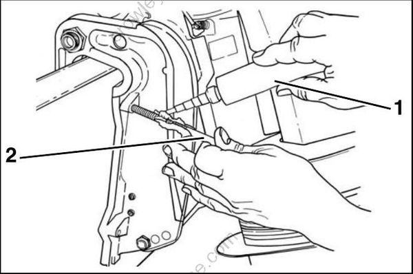
DR26500
- Marine sealer
- Bolt
Use Transom Mo unting Kit, P/N 394219, to protect the transom a nd he lp pre vent loss of outboard. The kit includes a transom mounting plate and hardware for fastening outboard to transom.
Install the mounting bolts through the stern brackets and transom. Install round backing plates and locknuts onto lower bolts and tighten securely.
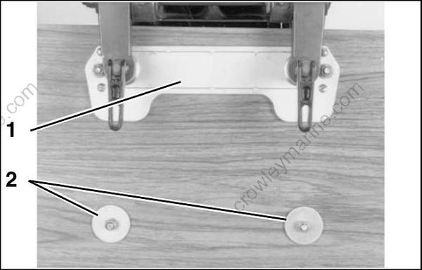
18961
- Transom mounting plate
- Round backing plates
The kit also includes clamp p ads, P/N 315774, which must be use d to secure mounting bolts in slots at the bottom of the outboard stern brackets.
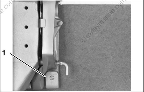
COB2505
- Clamp pad
Tiller Handle Attachment
The tiller handle can be removed with out tools to minimize required storage space.
To attach tiller handle to the outboard:
• Place shift rod through shift lever.
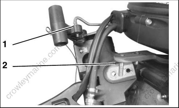
006515
- Shift rod
- Steering arm studs
• Place tiller handle bracket on steering arm studs and secure with hand nut.
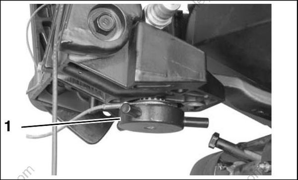
006516
- Hand nut
• Install washer and retaining clip on shift rod.
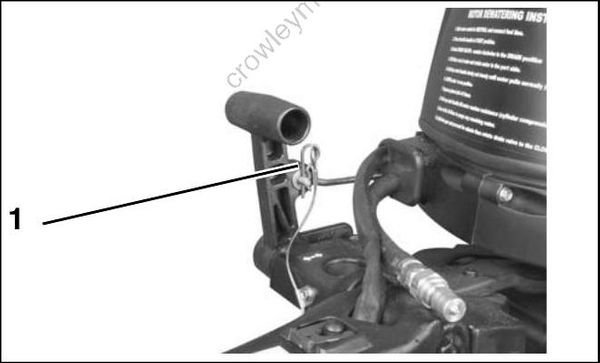
006517
- Retaining clip
