

Lower Cover Removal
Remove four carry handle screws and bushing caps. Remove carry handle and bushings.
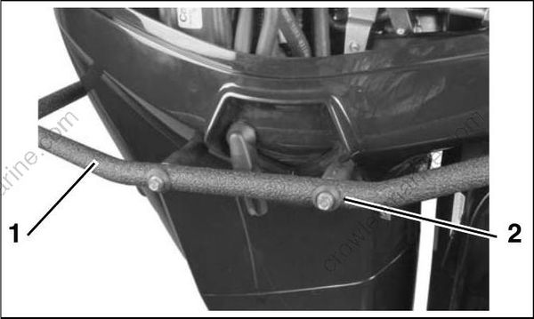
005061
- Carry handle
- Screws
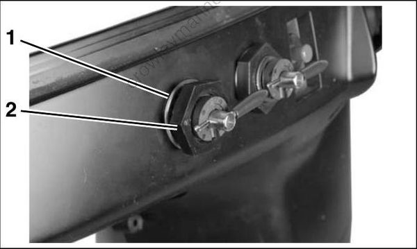
Remove nut and washer from dewater valves. Remove valves from cover.
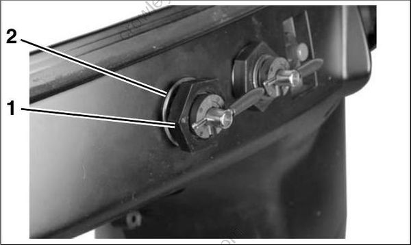
007849
- Nut
- Washer
Remove lower engine cover screws, including one at inside, top rear.
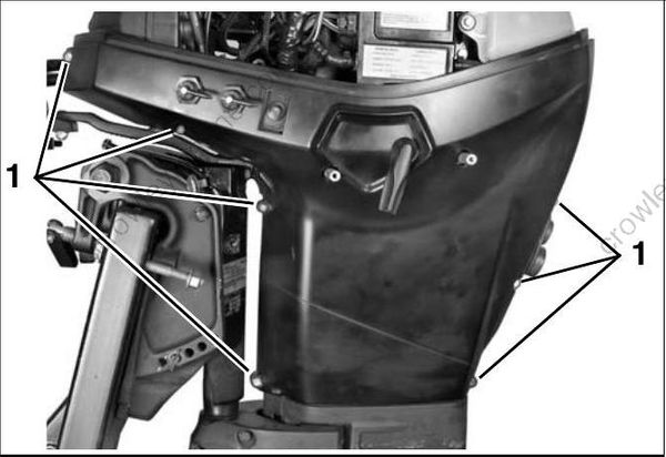
007845
- Cover screws
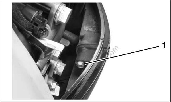
002150
- Top, rear cover screw
Loosen port cove r slightly , and disconnect fuel selector switch connector. Then, remove port cover.
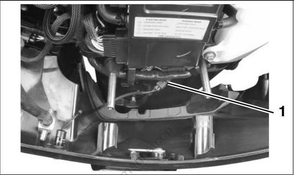
005063
- Fuel map switch connector
Tilt the starboard cove r to remove it below the grommet. Leave the grommet in place.
IMPORTANT: Cover and grommet installation is easiest if the grommet is in place first.
Lower Cover Installation
Installation of lower motor covers will be easiest if the following steps are performed in sequence:
Install air silencer on throttle body.
Secure grommet on cables with tie strap.
Slide starboard cover on t o grommet from the bottom and then into position on outboard.
Connect fuel map switch connector.
Place port side cover into position on outboard.
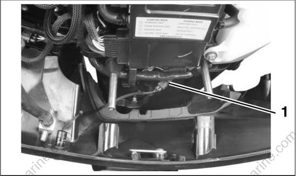
005063
- Fuel map switch connector
Start the screw above the exhaust relief grommet first. Tighten just enough to hold the grommet in place.
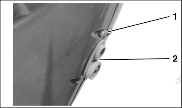
002157
- Start this screw first
- Exhaust relief grommet
Start the top front screw next an d draw cover halves together.
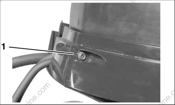
002165
- Start this screw second
Install remaining cover screws and tighten all screws to 24 to 36 in. lbs. (3 to 4 N·m).
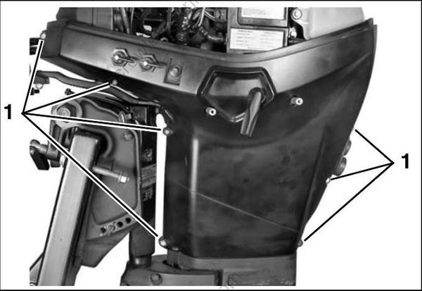
007845
- Cover screws
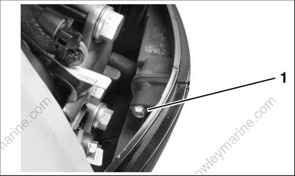
002150
- Top, rear cover screw
Place de-water valves through holes. Align tab of de-water valve with alignment notch as shown.
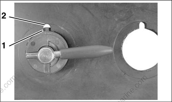
008177
- Tab
- Alignment notch
Install washer and nut. Tighten to a torque of 25 to 40 in. lbs. (3 to 4.5 N·m). Lever should point to the rear of the outboard when the valve is closed.
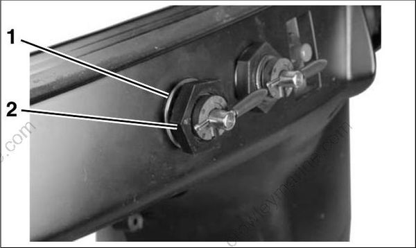
007849
- Washer
- Nut
Install long bushings on front cover pins and short bushings on rear pins. Install carry handle. Secure with bushing caps and screws.
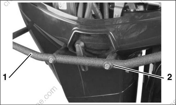
005061
- Carry handle
- Screws
Latch Handle Installation
Apply a light coat of Triple-Guard grease to latch handle shaft. Insert handle into lower cover.
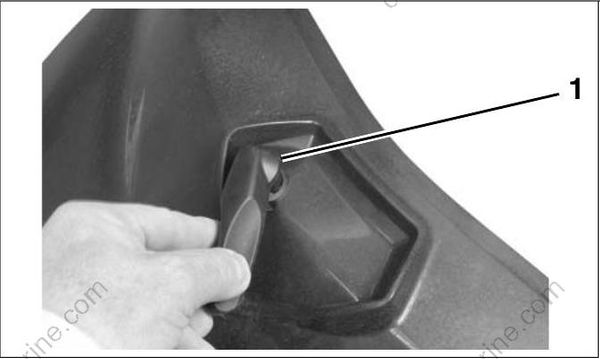
006470
- Triple-Guard grease
Apply Ultra-Lock to screw thread s. Place spring washer and hook into position and tighten screw to a torque of 180 in. lbs. (20 N·m).
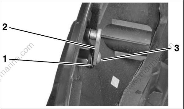
006471
- Spring washer
- Hook
- Screw
Fuel Selector Switch Installation
Place switch into position through cover.
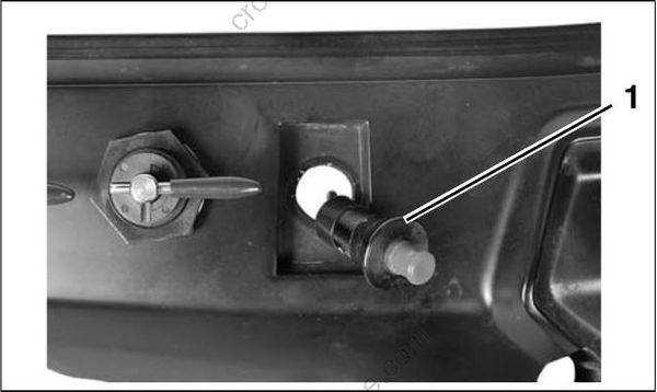
007846
- Fuel selector switch
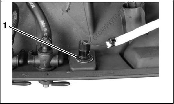
Install lock washer and nut on switch. Tighten nut to a torque of 10 to 16 in. lbs. (1 to 2 N·m).
007847
- Nut and washer
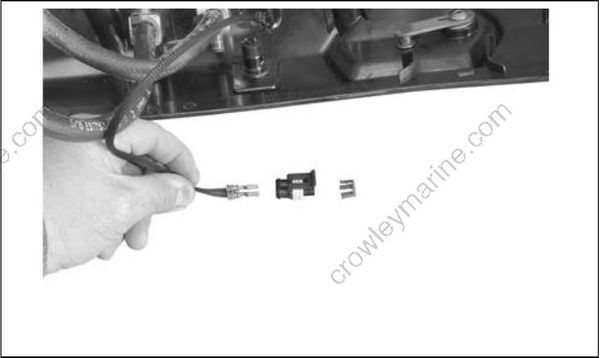
Install electrical connector. Refer to AMP Connectors on p. 128.
006472
De-Water Valve Service
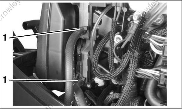
Install drain valve hoses on reed plate and secure with tie straps.
005062
- Drain valve hoses
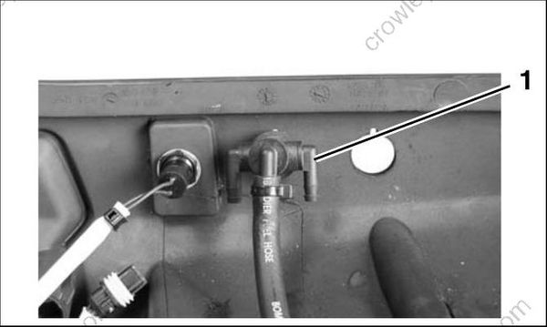
Install drain valve through cover with outlets pointed down.
007848
- Drain outlet
Install washer and nut. Tighten to a torque of 25 to 40 in. lbs. (3 to 4.5 N·m). Lever should point to the rear of the outboard when the valve is closed.
007849
- Washer
- Nut
