

Temperature Sender Servicing
Removal
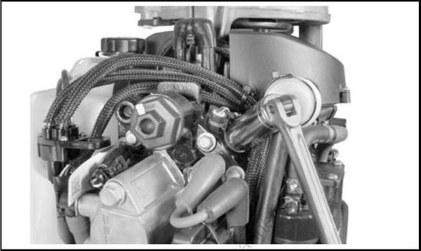
Loosen sensor and remove by hand. Use care to avoid breaking threads.
008346
Clean sensor threads, sensor, and sensor cavity.
Installation
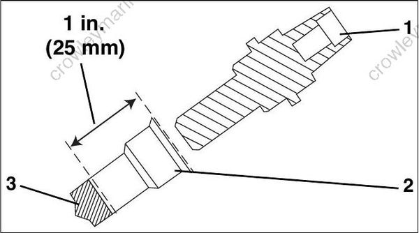
Fill bottom of sensor cavity with 0.7 cc of Thermal Joint Compound, P/N 322170. Sensor cavity should be filled to 1 in ch (25 mm) below the top edge of the cavity.
Install sensor. DO NOT use gasket sealing compound. SLOWLY tighten temperature sensor to a torque of 50 to 70 in. lbs. (5.6 to 8.0 N·m).
007049
- Temperature sensor
- Sensor cavity
- Thermal joint compound
Wait 10 minutes for trapped air to bleed from cavity. Th ermal compo und may seep past threads. Retighten sensor.
Thermostat Servicing
Disassembly
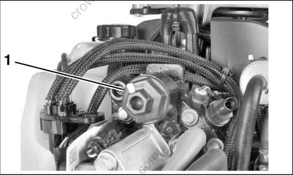
Remove the thermostat cover and O-ring from cylinder head.
008347
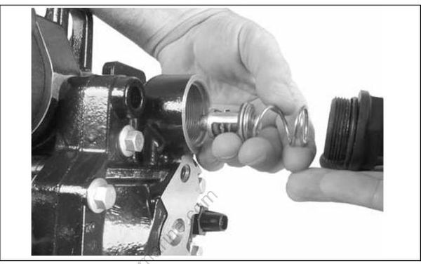
Remove spring, thermostat, and gasket.
002444
Remove the cylinder head if cylinder head thermostat seal requires replacement. Place new seal in the cylinder head with side marked “T O CYL HEAD” facing thermostat. Refer to Cylinder Head Installation on p. 197.
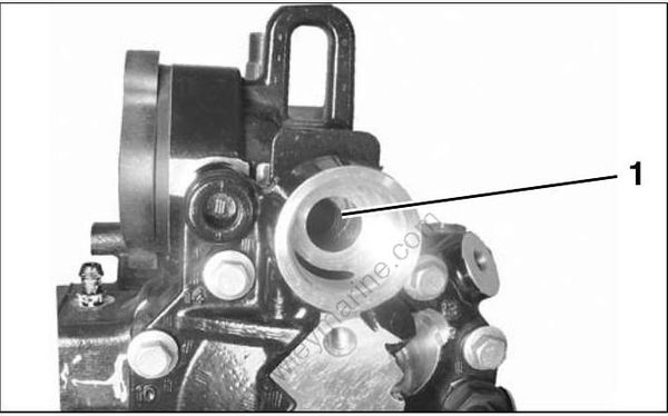
002445
- Cylinder head seal
Inspection
Inspect all parts for cracks, heat damage, or signs of corrosion. Re place damaged p arts. Clean debris from housing and parts.
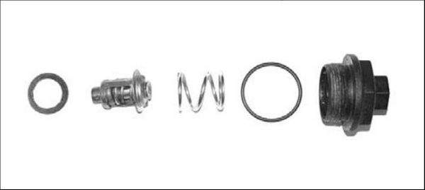
000756
Assembly
Assembly is the rever se of disassemb ly. Pa y close attent ion when pe rforming the following additional tasks.
Coat t hreads of thermost at cover with Gasket Sealing Compound and install new O-ring. Install and tighten cover to a torque of 120 to 144 in. lbs.
(13.5 to 16 N·m).
Pressure Relief Valve Servicing
The pressure relief valve assembly should be serviced at the same time as the thermostat.
Disassembly
Remove screws and cove r from pressure valve assembly.
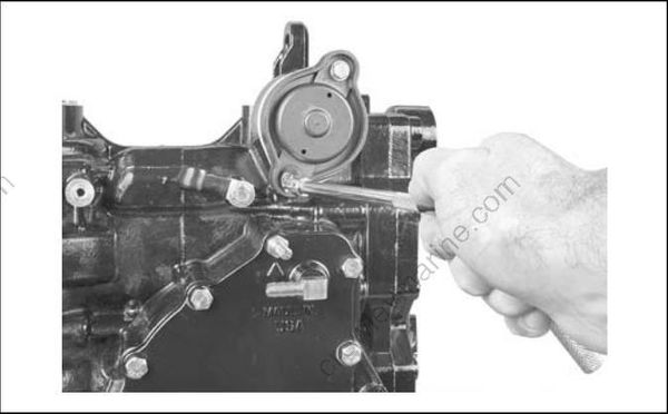
002443
Remove the pressure relief valve assembly.
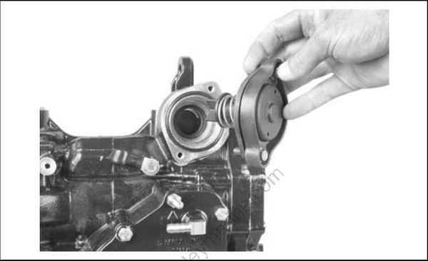
002459
