

Steering Friction Adjustment
Tiller models are equipped with a steering friction adjustment. Steering friction is not required when remote steering is used.
Adjust steering friction with outboard mounted to boat by loosening or tightening the adjustment screw. Steering friction should be adjusted so a slight drag is felt when turning.
Do not overtighten. The steering friction screw is not intended to allow “hands off” steering.
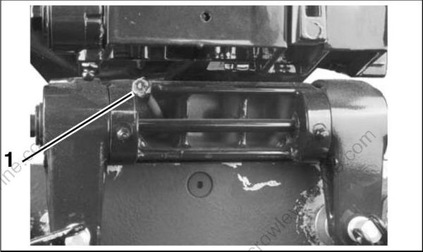
- Steering friction adjustment—Manual tilt models 001256
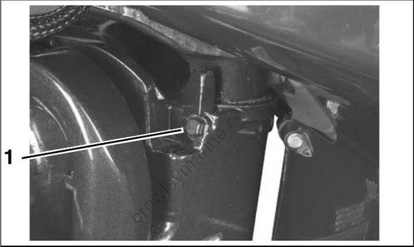
- Steering friction adjustment—Power tilt models 005116
Throttle Friction Adjustment
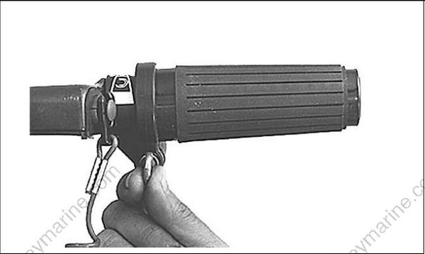
Tiller models are equipped with a throttle friction adjustment knob located on the steering handle. Tighten the knob to reduce the effort required to hold a throttle setting. Turn the knob:
• clockwise to increase friction
• counterclockwise to decrease friction
Tighten knob only enough to hold throttle at a constant engine speed. Overtightening will prevent quick throttle change incase of emergency
002191
Tilt Limit Switch Adjustment (75 – 90 HP)
If the outboard does not clear all boat parts when tilted fully or turned side to side, safety related parts could be damaged in the course of such outboard movement. Injuries could result from loss of boat control.
Adjust the tilt limit switch o n all new outboard installations.
Check the clearance between outboard(s) and the boat’s motor well and transom area. Tilt out board(s) to highest point of clearance and turn the steering system lock to lock.
If the outboard contacts the boat's motor well when fully tilted, adjust the tilt limit cam t o reduce full-tilt position.
The tilt limit cam will not prevent the outboard from overriding the adjustment if the outboard is tilted manually.
DR3916
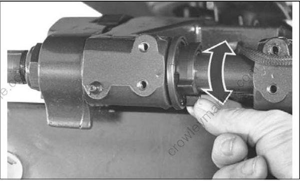
Place the outboard in normal operating position. Rotate the LOWER adjustment tab UP to reduce the maximum tilt. Rot ate the UPPER adjustment tab DOWN to increase the maximum tilt position.
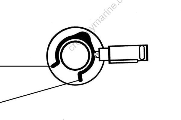
- Lower adjustment tab
- Upper adjustment tab
DR4268
Check the adjustment by tilting the outboard fully. Repeat this procedure until the tilt limit switch stops the outboard's upward travel before it contacts the motor well.
To pre vent da mage to equipment, provide additional motor we ll clearance when needed. Co n sider either changing the outboard mounting position or modifying the boat if the possibility for interference and damage exists.
Adjusting the tilt limit cam will NOT prevent the outboard from tilting fully and contacting the motor well if the gearcase hits an object at high speed. Such contact could damage the outboard and boat and injure boat occupants.
Trim Sending Unit Adjustment (40 – 60 HP)
The sending unit eccentric cam must be adjusted so that the gauge needle is aligned with the lowest gauge mark with the outboard trimmed all the way DOWN.
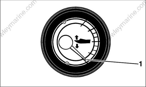
- Lowest gauge mark DR2827
Check if the gauge needle is a b over below the lowest gauge mark. Tilt engine UP and engage trailering lock.
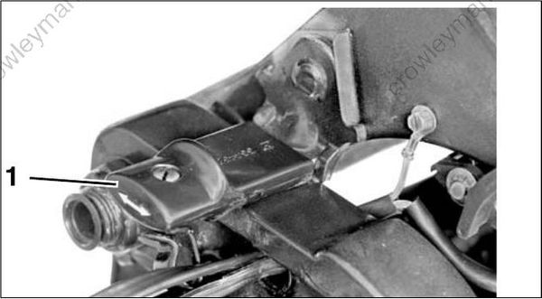
- Trailering lock 18954
To avoid personal injury, do not adjust the sending unit eccentric cam while the engine is being tilted.
When the outboard is trimmed all the way DOWN, the sending unit lever touches the eccentric cam just forward of the top of the cam at the contact point.
Loosen cam screw a nd rot ate eccentric cam to adjust full down gauge position:
• If the needle was above the lowest mark, move the thick part of the cam T OWARD the contact point. Tighten the screw, and recheck the gauge reading.
• If the needle was below the lowest mark, move the thick part of the cam AWAY from the contact point. Tighten the screw, and recheck the gauge reading
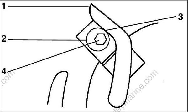
- Lever
- Eccentric cam
- Contact point
- Cam screw
DR5090
Tighten eccentric cam retaining screw an d check needle position at full trim DOWN.
Trim Sending Unit Adjustment (75 – 90 HP)
Tilt the outboard and engage the tilt support.
Temporarily install a thrust rod, P/N 436541, in the number 3 hole.
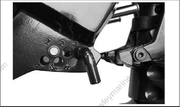
29072
Loosen the sending unit screws, to allow the sending unit to pivot.
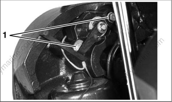
27339
Disengage the tilt support. Lower the outboard against the thrust rod.
Observe the trim gauge. If the needle does not show center position, tilt the outboard up a nd adjust the sending unit by pivoting it up or down.
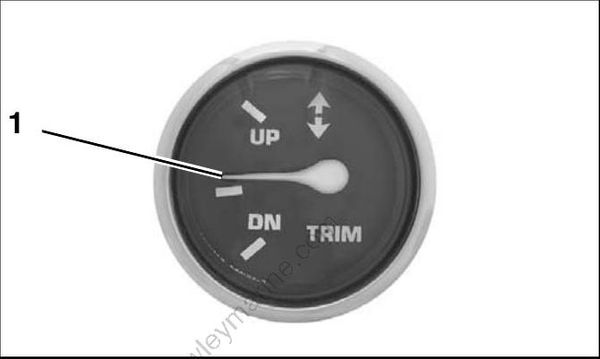
- Needle at center position 000662
Lower the outboard against the thrust rod to check adjustment. Repeat adjustment, if necessary. After adjustment is correct, tilt the outboard u p, tighten the two sending unit screws, and remove the thrust rod.
Trim Limiter Rod
The trim limiter rod prevents excessive trim down. As the engine is trimmed to the full down position, the bow of the boat goes deeper into the water.
• If the trim limiter rod is left out, the bow could plow into the water causing the boa t to “bow steer” resulting in a loss of control.
• If the trim limiter rod is set too far out, the propeller could ventilate, resulting in poor acceleration when the boat is coming onto plane.
Set the trim limiter rod to pre vent excessive trim down and provide good acceleration. The trim limiter rod can be used to prevent the gearcase or spray deflector from contacting the transom.
When the outboard is returned to the customer, the trim limiter rod must be installed and in the same location as it was when the motor was brought in for
service. Leaving the trim limiter rod out, or changing the adjustment, could allow the motor to unexpectedly trim in too far and cause loss of control.
Trim Tab Adjustment
Improper trim tab adjustment can cause difficult steering and loss of control.
A propeller will generate steering torque when the propeller shaft is not running parallel to the water’s surface. The trim tab is adjustable to compensate for this steering torque.
IMPORTANT: A single trim t ab adjustment will relieve steering effort under only one set of speed, outboard angle and load conditions. No sing le adjustment ca n relieve steering effort under all conditions.
If the boat pulls to the left or right when its load is evenly distributed, adjust the trim tab as follows:
• With the remote control in NEUTRAL and the engine OFF, loosen the trim tab screw.
• If the boa t pulled to the right, move rear of the trim tab slightly to the right.
• If the boat pulled to the left, move rear of the trim tab slightly to the left.
Tighten the trim tab screw as follows: • 40 – 90 HP: 35 to 40 ft. lbs. (47 to 54 N·m)..
- Trim tab screw COA3663
Test the boat and, if needed, repeat the procedure until steering effort is as equal as possible.
Outboards with High Transom Heights
The trim tab may be above the surface o f the water when the outboard is trimmed out. Steering effort might increase. Lower the trim setting to submerge the trim t ab and t o reduce steering effort.
Dual Standard Rotation Outboards
Move both trim t abs equally and in the same direction.
Dual Outboards, One Counter and One Standard Rotation
Set both trim tabs to the center position.
Dual-Outboard Alignment
Dual outboards must b e connected with a tie bar and adjusted to align the outboards for correct water flow to the gearcases and propellers.
Incorrect outboard alignment could cause one or more of the following:
• Propeller ventilation
• Reduction of top speed
• Improper boat tracking
• Engine overheat and powerhead damage
Follow the instructions provided by t he tie -bar manufacturer for tie bar installation and adjustment.
Measure Alignment
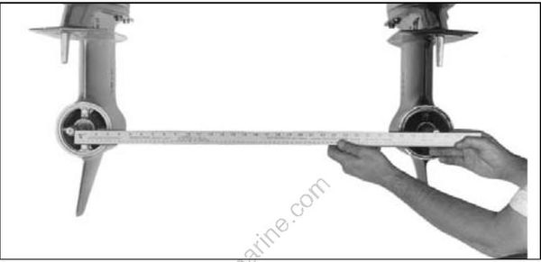
The “toe-in” (gearcase lea ding edge s closer together than propeller shaft centers) o r “toe-out” (gearcase leading edges farther apart than propeller shaft centers) is determined as follows:
• Position outboards straight with the anti-ventilation plates parallel with the bottom of the boat.
• Measure between propeller shaft centers.
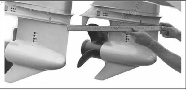
6340
Alignment Adjustment
Various boat/motor combinations respond differently to dual-outboard alignments. Each application must be thoroughly tested until the ideal combination of performance, steering, and cooling is found.
A common practice is to set-up the outboards parallel, or with a small a mount of “toe-out,” a nd adjust inward until best results are achieved.
• A typical set-up, with out boards mounted directly on the transom, often runs best with a slight amount of “toe-in.”
• Outboards mounted be hind the transom on motor brackets usually require parallel alignment or “toe-out.”
Adjust the outboard alignments by adjusting tie bar. Follow the tie bar manufacturer’s adjustment procedures.
Check steering operation. Make sure that t he steering system operates properly at various trim angles.
Confirm Alignment
To confirm proper alignment, perform the following steps:
• Water test the boat.
• Monitor the water pressure for both outboards.
• Run the boat at various trim angles.
• Perform steering maneuvers and vary the throttle settings.
• Monitor boat and outboard performance.
A sudden loss of water pressure or excessive propeller ventilation on one or both outboards may indicate a misalignment of the gearcases. Reset the outboard alignment and retest.
