

COMPRESSION TESTING
Start and run outboard until it achieves operating temperature, then shut OFF.
Disconnect crankshaft position sensor (CPS) connector. Remove all spark plugs. Advance throttle linkage to WOT.
Install compression tester’s hose attachment into spark plug hole (14 mm threads).
While cranking outboard with starter, note maxi mum pressure reading on gauge. Repeat procedure for each cylinder.
If engine shows a variation greater than 15 psi (100 kPa) between cylinders, check for:
- damaged cylinder head
- damaged pistons
- broken or stuck piston rings
- scored cylinder walls
Return throttle to idle position and reconnect CPS connector. Replace sp ark plugs. Refer t o S
park Plug Indexing on p. 42.
POWER HEAD REMOVAL
2-Cylinder Models
Protect against hazardous fuel spray. Before starting any fuel system service, carefully relieve fuel system pressure. Refer to Relieving Fuel System Pressure on p. 142. To prevent accidental starting while servicing, twist and remove spark plug leads
Remove lower motor covers. Refer to Lower Cover Removal on p. 50. Disconnect power trim connectors an d exhaust water valve electrical connector (60, 65).
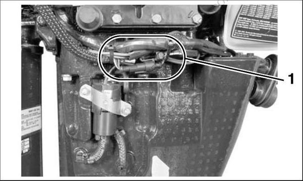
- Connectors
008429
Disconnect cooling water hoses from exhaust housing.
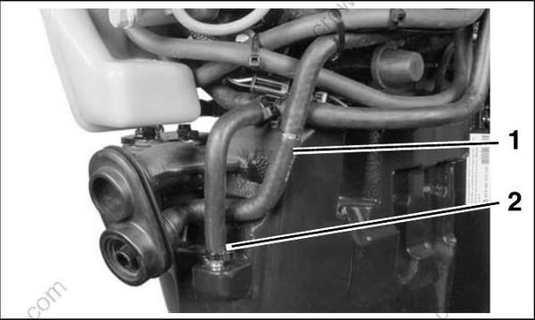
- Overboard indicator hose
- Drain hose
004298
Remove pin and washer from shift rod lever to release the lower shift rod.
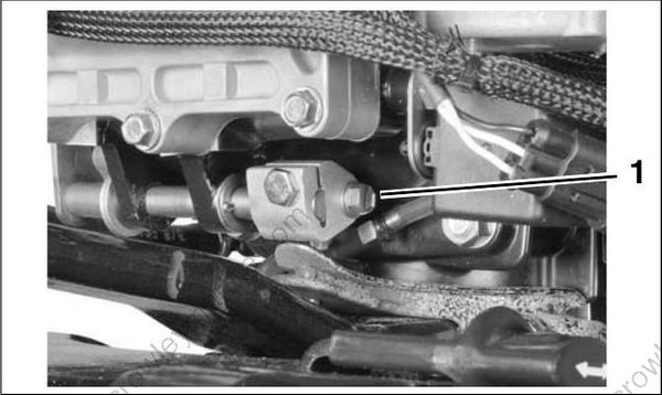
- Shift rod screw
002171
ROPE START MODELS
Remove throttle cable and tiller shift rod.
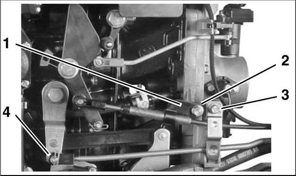
- Cable anchor
- Anchor screw
- Cable retainer
- Shift rod retainer
006526m
Remove the recoil starter housing and starter ratchet. Refer t o RECOIL STARTER REMOVAL on p. 363
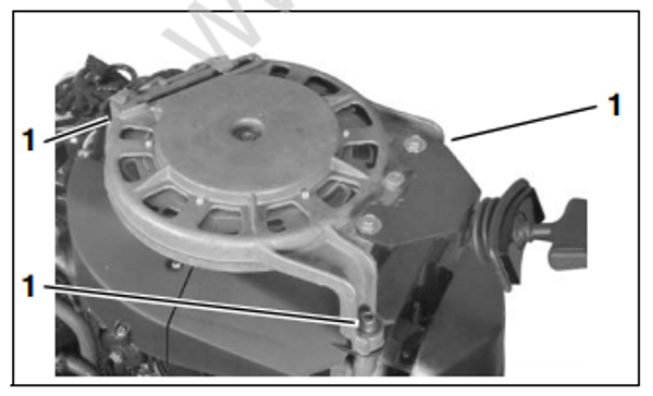
- Starter housing screws (3)
002515
ALL MODELS
Install Lifting Fixture, P/N 396748, on flywheel and seat the three screws completely.
Be sure to use only the 1 1/8 in. (short) screws, P/N 398067, included with the tool to avoid damage to electronic components under the flywheel.
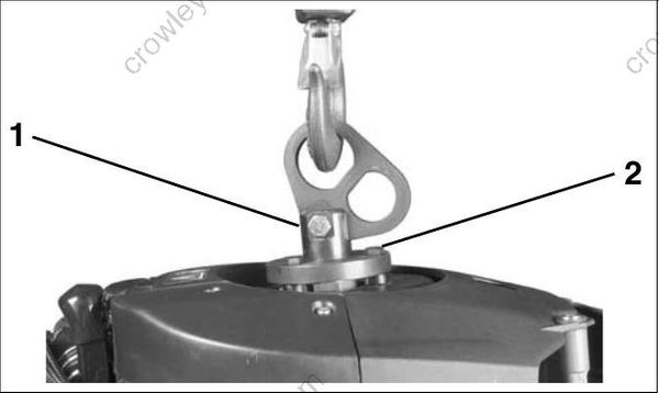
- Lifting fixture
- 1 1/8 in. screws
002098
Fasten appropriate chain hook to eye of tool an d support weight of power head with hoist. Loosen the screws holding the exhaust water valve to the exhaust housing. Move water valve aside and remove the eight exhaust housing to power head screws.
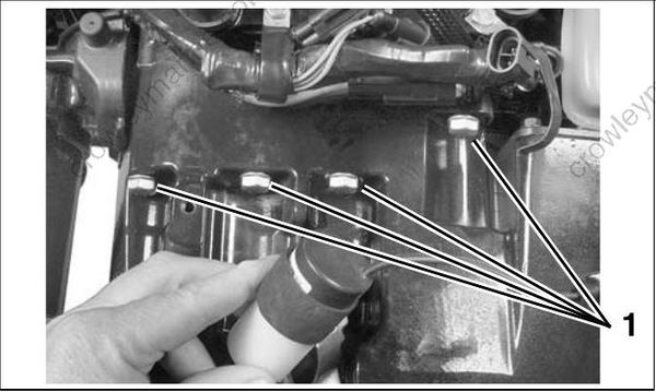
- Power head screws
004292
Use a suitable tool to carefully separate the power head from exhaust housing.
IMPORTANT: Do not damage the power head or exhaust housing mating surfaces.
3-Cylinder Models
Protect against hazardous fuel spray. Before starting any fuel system service, carefully relieve fuel system pressure. Refer to Relieving Fuel System Pressure on p. 142. To prevent accidental starting while servicing, twist and remove spark plug leads.
Remove lower motor covers. Refer to Lower Cover Removal on p. 50. Disconnect power trim connectors.Disconnect power trim connectors.
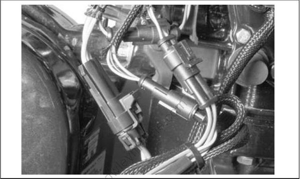
002152
Remove pin and washer from shift rod lever to release the lower shift rod.
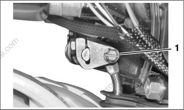
- Shift rod pin
Remove six retaining screws and exhaust relief muffler.
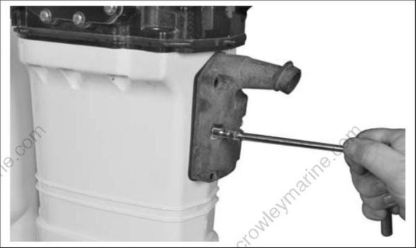
002159
Install Lifting Fixture, P/N 396748, on flywheel and seat the three screws completely.
Be sure to use only the 1 1/8 in. (short) screws, P/N 398067, included with the tool to avoid damage to electronic components under the flywheel
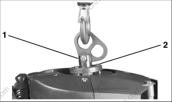
- Lifting fixture
- 1 1/8 in. screws
002098
Fasten appropriate chain hook to eye of tool a nd support weight of power head with hoist.
Remove the small power head screw at rear.
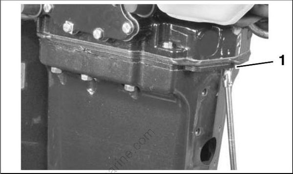
- Rear small power head screw
002160
Remove remaining four small power head screws, six large power head screws, and the upper mount screws.
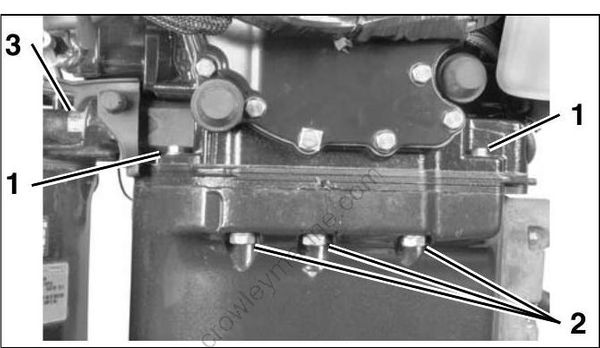
- Small power head screws
- Large power head screws
- Upper mount screws
002153
Use a suitable tool to carefully separate the power head from exhaust housing.
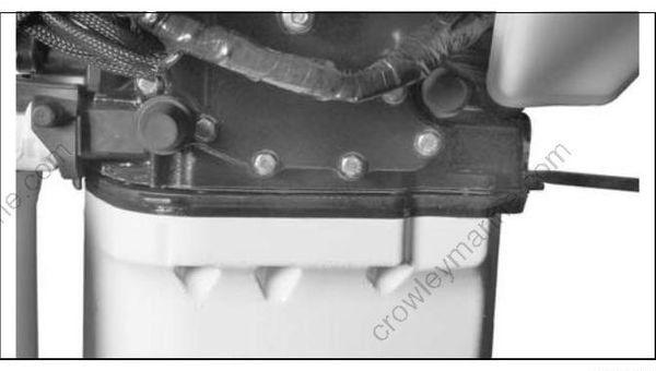
IMPORTANT: Do not damage the power head or exhaust housing mating surfaces.
POWER HEAD DISASSEMBLY
Systems Removal
To simplify reassembly and wiring installation, lay out the various screws and clamps in the order of their proper location. Remove the electric starter. Refer to Starter Removal on p. 115.
Remove the oil tank. Refer to Oil Tank Assembly on p. 169. Remove fuel pump assemblies, fuel manifolds, and filter. Refer to FUEL COMPONENT SERVICING on p. 142. Remove EMM, then electrical harness assembly. Label connectors for reassembly locations. Re fer to EMM SERVICING on p. 70. Remove flywheel and stator. Refer to FLYWHEEL AND STATOR SERVICING on p. 110. Remove ignition coils and fuel injectors. Refer to IGNITION COIL SERVICING on p. 112 and Fuel Injector Service on p. 146. IMPORTANT: Mark injectors f or cylinder location before removal. All injectors must be installed in their original location. Improper injector installation can result in power head failure. Remove all oil distribution and recirculation hoses. Remove throttle linkage. Refer to Throttle Linkage Removal on p. 194. Remove shift linkage. Refer to Shift Linkage Removal on p. 194. Remove the throttle body and reed plate assemblies. Refer to Intake Manifold Service on p. 149. Remove pres sure valve assembly. Refer to PRESSURE RELIEF VALVE SERVICING on p. 183.
