

OUTBOARD WILL NOT START
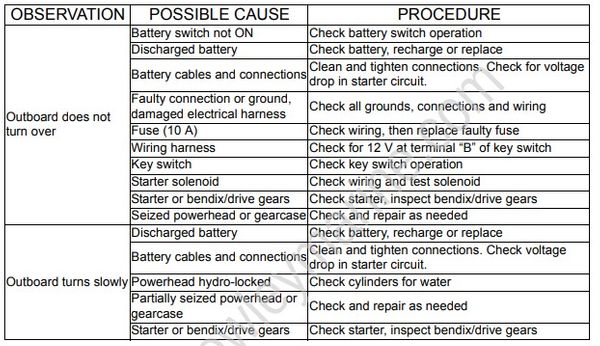
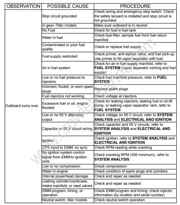
OUTBOARD HARD TO START
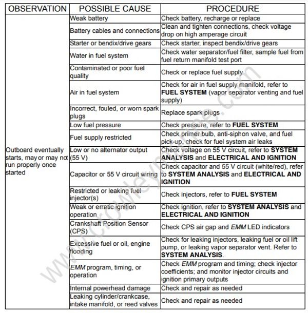
OUTBOARD WILL NOT SHUT OFF
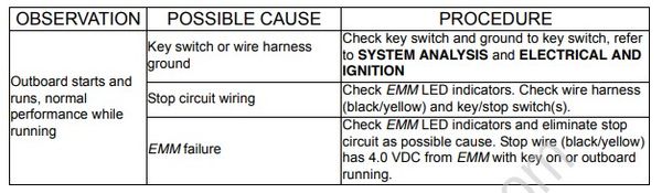
OUTBOARD STARTS AND STALLS
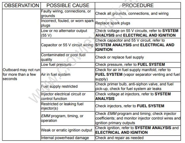
OUTBOARD STARTS, LOW MAXIMUM RPM

EXCESSIVE SMOKING
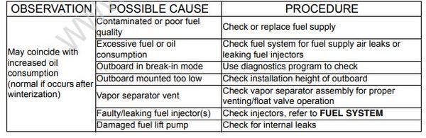
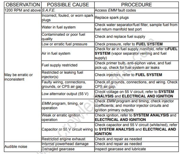
OUTBOARD SURGES, RUNS ROUGH
Hose Routing and Water Flow Diagram 15 – 30 HP E-TEC Inline 2 Cylinder
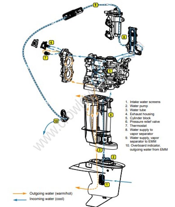
- Intake water screens
- Water pump
- Water tube
- Exhaust housing
- Cylinder block
- Pressure relief valve
- Thermostat
- Water supply to vapor separator
- Water supply, vapor separator to EMM
- Overboard indicator, outgoing water from EMM
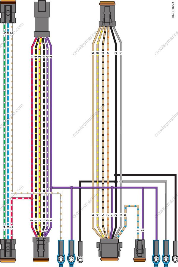
MWS Instrument Wiring Harness
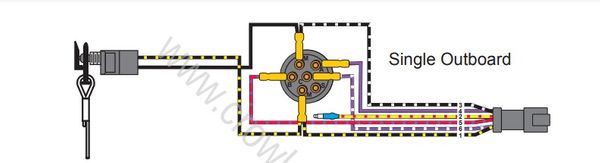
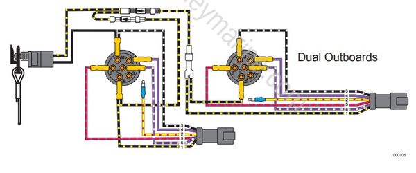
Lanyard Switch / Emergency Stop Circuits
Single Outboard
Dual Outboards
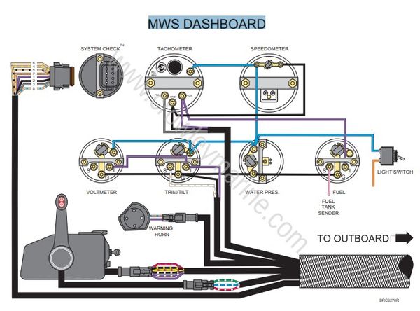
MWS Key Switch and Neutral Safety Switch

MWS DASHBOARD
Tiller Harness 15 – 30 HP E-TEC
- Tiller to Engine Harness Connector
- Trim Switch Connector
- Trim Switch
- Power Connector (Trim Switch)
- Start Switch
- Stop Switch
- Touch Troll Switch

Evinrude E-TEC
EMM LED Diagnostic Indicators
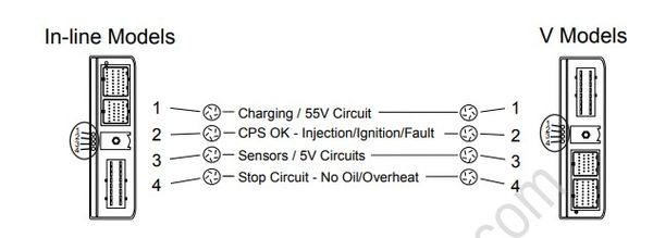
For more information, refer to SYSTEM ANALYSIS in the Service Manual.
KEY ON: LED’s illuminate to indicate circuit function
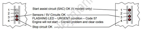
FLASHING LED – URGENT overheat or no oil condition
Engine will not start – Correct problem and clear codes
No LED’s ON indicates EMM not receiving battery voltage or Recoil Start model.
STARTING : LED’s illuminate to indicate circuit function
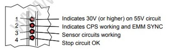
RUNNING : LED’s illuminate to indicate circuit fault
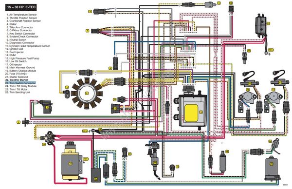
15 – 30 HP E-TEC
- Air Temperature Sensor
- Throttle Position Sensor
- Crankshaft Position Sensor
- Stator
- Tiller Arm Connector
- CANbus Connector
- Key Switch Connector
- SystemCheck Connector
- Neutral Switch
- Diagnostic Connector
- Cylinder Head Temperature Sensor
- Ignition Coil
- Fuel Injector
- EMM
- High Pressure Fuel Pump
- Low Oil Switch
- Oil Injector
- Main Harness Ground
- Battery Charge Module
- Fuse (10 Amp)
- Starter Solenoid
- Trim Switch Connector
- Trim / Tilt Relay Module
- Trim / Tilt Motor
- Trim Sending Unit
EVINRUDE 15 – 30 HP EMM SERVICE CODE CHART
| CODE | EMM CIRCUIT/SENSOR | INTERNAL SENSOR | S.A.F.E | SHUT DOWN | EMM LED DISPLAY | TIME TO ACTIVATE | SENSOR: CIRCUIT VOLTAGE / RESISTANCE (Ω) / INFORMATION |
|---|---|---|---|---|---|---|---|
| 11 | Throttle Position Sensor (TPS) out of idle range |
- | 2 seconds | TPS Voltage > 1.71 V with key ON (or cranking). Becomes stored fault when outboard starts. When both hard and stored faults are present, check for improperly adjusted throttle cable. |
|||
| 12 | Throttle Position Sensor (TPS) circuit fault |
LED 3: OFF (Cranking) / ON (Running) | 0.8 seconds | TPS Voltage: < 0.14V, or > 4.92V. Engine limited to idle speed. Check sensor resistance—3000 to 7000 Ω (between pins A and B) & 4000 to 8000 Ω (between pins A and C) |
|||
| 13 | TPS below range | LED 3: OFF (Cranking) / ON (Running) | 8 seconds | TPS Voltage < 0.2V. Check linkage and IDLE stop. | |||
| 14 | TPS above range | LED 3: OFF (Cranking) / ON (Running) | 8 seconds | TPS Voltage > 4.85V. Check linkage and WOT stop. | |||
| 15 | ROM (EMM program) | ✔ | - | - | ROM “CHECKSUM” failure. Check software program number in EMM. Reload or replace with proper program. | ||
| 16 | Crankshaft Position Sensor (CPS) Intermittent loss of SYNC |
LED 2: OFF (Cranking) LED 3: ON (Running) |
10 instances | EMM counts losses of synchronization with crankshaft sensor. Check CPS mounting and resistance. Air gap range: 00.036 to 0.110in. (1 to 2.8mm), nominal 0.073in. (1.85mm) Resistance: 560 Ω ± 10% @ 77°F (25°C) | |||
| 17 | 55V circuit BELOW range | ✔ | ✔ | LED 1: ON (Running) | 1 minute | System Voltage < 45V. Engine limited to 1200 RPM. Perform stator/charging tests. | |
| 18 | 55V circuit ABOVE range | ✔ | ✔ | LED 1: ON (Running) | 1 minute | System Voltage > 57V. Engine limited to 1200 RPM. Perform stator/charging tests. Check for loose connections in 55V circuit. |
|
| 19 | Start-in-gear | LED 3: OFF (Cranking) | - | Attempted engine start while in gear. Engine will not start. | |||
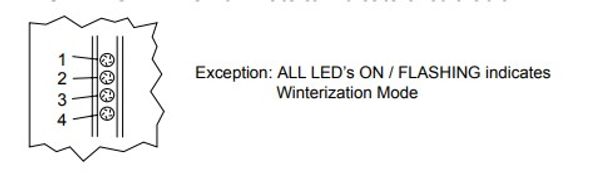
| 21 | Winterization activated | All LEDs FLASHING | - | Engine is speed limited, and stops after 360 oil pulses. Refer to Maintenance or Operator’s Guide. | |||
| 23 | EMM Temperature Sensor circuit fault | ✔ | LED 3: OFF (Cranking) / ON (Running) | 8 seconds | EMM Temperature < -71° F (-57.4° C), or > 313° F (156° C). | ||
| 24 | EMM Temperature BELOW range | ✔ | LED 3: OFF (Cranking) / ON (Running) | 8 seconds | EMM Temperature < -22 ° F (-30° C). | ||
| 25 | EMM Temperature ABOVE range | ✔ | ✔ | LED 4: ON (Running) | 8 seconds | EMM Temperature > 194°F (90°C). Engine limited to 1200 RPM. See Code 29. | |
| 26 | 12V circuit BELOW range | ✔ | LED 1: ON (Running) | 5 minutes | Battery voltage < 12.5V. Perform stator/charging tests. | ||
| 27 | 12V circuit ABOVE range | ✔ | LED 1: ON (Running) | 5 minutes | Battery voltage > 15.5V. Check battery connections and wiring. | ||
| 29 | EMM Temperature OVER range | ✔ | ✔ | LED 4: FLASHING | 4 seconds | EMM Temperature > 212° F (100° C). Engine SHUTDOWN. Will NOT restart until EMM temperaturereturns to operating range. Check outboard and EMM cooling systems. | |
| 31 | Engine temperature OVER range | ✔ | LED 4: FLASHING | 8 seconds | Engine Temperature > 248° F (120° C) Engine SHUTDOWN. Check cooling system. Check temperature sensor resistance—9000 to 11000 Ω @ 77°F (25°C). |
||
| 33 | Critical NO OIL detected | ✔ | ✔ | LED 4: FLASHING | 3 hours | Outboard has run three hours with code 34 or 117. Engine SHUTDOWN. Will restart and run for 1 minute intervals. | |
| 34 | Oil injection pump circuit OPEN | ✔ | LED 4: ON (Running) | 4 seconds | Engine limited to 1200 RPM. Check oil injection pump circuit resistance—22 Ω. | ||
| 40 | Engine Temperature ABOVE range–Low speed | ✔ | LED 4: ON (Running) | 8 seconds | Engine Temperature > 212° F (100° C) below 3500 RPM. | ||
| 41 | Engine Temperature Sensor circuit fault | LED 3: OFF (Cranking) / ON (Running) | 8 seconds | Engine Temperature < -15° F (-26.2° C), or > 332° F (166.5° C). Check 5V circuit and ground (NEG), and sensor resistance—9000 to 11000 Ω @ 77°F (25°C). |
|||
| 42 | Engine Temperature BELOW range | LED 3: OFF (Cranking) / ON (Running) | 8 seconds | Engine Temperature < -4° F (-20° C). Check engine temperature and sensor resistance. | |||
| 43 | Engine Temperature ABOVE range | ✔ | LED 4: ON (Running) | 8 seconds | Engine Temperature > 194° F (90° C) above 3500 RPM Engine limited to 1200 RPM. Check cooling system. |
||
| 44 | Barometric Pressure (BP) Sensor circuit fault | ✔ | - | 8 seconds | Pressure < 3.9 in. Hg (13.3 kPa), or > 35.1 in. Hg (119.0 kPa). Check atmospheric condition for comparison. Clear code and retest. |
||
| 45 | BP Sensor BELOW range | ✔ | - | 8 seconds | Pressure < 20.7 in. Hg (70 kPa). | ||
| 46 | BP Sensor ABOVE range | ✔ | - | 8 seconds | Pressure > 31 in. Hg (105 kPa). | ||
| 47 | Air Temperature (AT) circuit fault | LED 3: OFF (Cranking) / ON (Running) | 8 seconds | Air temperature < -58° F (-49.9° C), or > 218° F (103.2° C). Check 5V circuit and ground (NEG), and sensor resistance—9000 to 11000 Ω @ 77°F (25°C). |
|||
| 48 | Air Temperature BELOW range | LED 3: OFF (Cranking) / ON (Running) | 8 seconds | Air temperature < -22° F (-30° C). | |||
| 49 | Air Temperature ABOVE range | LED 3: OFF (Cranking) / ON (Running) | 8 seconds | Air temperature > 158° F (70° C). | |||
| 51 | Fuel injector circuit #1 OPEN | LED 2: ON (Running) | 8 seconds | Check injector/circuit resistance—2 to 3 Ω @ 72°F (22°C). | |||
| 52 | Fuel injector circuit #2 OPEN | LED 2: ON (Running) | 8 seconds | Check injector/circuit resistance—2 to 3 Ω @ 72°F (22°C). | |||
| 57 | High RPM with low TPS setting | ✔ | ✔ | LED 3: FLASHING | 10 seconds | TPS < 5% and RPM > 3000. Engine SHUTDOWN. Will NOT restart until code has been cleared. The problem could be caused by uncontrolled fuel entering the engine. DO NOT attempt to start the outboard until the problem has been found and repaired. | |
| 58 | Operating temperature not reached | LED 3: OFF (Cranking) / ON (Running) | 9 minutes | Engine temperature < 104° F (40° C) with engine speed < 2300 RPM. Check thermostat and pressure relief valve. |
|||
| 61 | Fuel injector circuit #1 SHORTED | LED 2: ON (Running) | 8 seconds | Check injector/circuit resistance—2 to 3 Ω @ 72°F (22°C). | |||
| 62 | Fuel injector circuit #2 SHORTED | LED 2: ON (Running) | 8 seconds | Check injector/circuit resistance—2 to 3 Ω @ 72°F (22°C). | |||
| 78 | Sensor supply voltage fault | ✔ | LED 3: OFF (Cranking) / ON (Running) | 10 seconds | Sensor voltage < 4.75 V. Check sensors and related wiring. Check for pinched or chafed wiring. | ||
| 81 | Ignition timing circuit #1 OPEN | LED 2: ON (Running) | 10 instances | EMM counts failed ignition events. Check wiring. Test with known good ignition coil. | |||
| 82 | Ignition timing circuit #2 OPEN | LED 2: ON (Running) | 10 instances | EMM counts failed ignition events. Check wiring. Test with known good ignition coil. | |||
| 91 | Fuel pump circuit OPEN | LED 2: ON (Running) | 8 seconds | Check pump/circuit resistance—2 to 3 Ω @ 77°F (25°C). | |||
| 94 | Fuel pump circuit SHORTED | LED 2: ON (Running) | 2 seconds | Check pump/circuit resistance—2 to 3 Ω @ 77°F (25°C). | |||
| 101 | Ignition timing circuit #1 SHORTED | LED 2: ON (Running) | 5 events-low speed 2 events-high speed |
EMM counts failed ignition events. Check wiring. Test with known good ignition coil. | |||
| 102 | Ignition timing circuit #2 SHORTED | LED 2: ON (Running) | 5 events-low speed 2 events-high speed |
EMM counts failed ignition events. Check wiring. Test with known good ignition coil. | |||
| 117 | Critical LOW OIL detected | ✔ | ✔ | LED 4: ON (Running) | 6700 Pulses | EMM counts oil pump pulses after LOW OIL switch closes. Engine limited to 1200 RPM. Stop outboard and add oil to tank. Warning resets after three oil pump pulses. |
|
| 120 | Oil level sensor OPEN | ✔ | LED 4: ON (Running) | 4 seconds | Check switch continuity—open below 1/4 capacity, closed above 1/4 capacity. |
Always note service codes before clearing codes. Clear stored codes using diagnostic software. Clearing some codes requires turning EMM “OFF” and then “ON” again.
