

POWER HEAD INSTALLATION
Apply Permatex No. 2 to both sides of a new base gasket around the exhaust port only. Install gasket on adapter. To ensure proper sealing, mating surfaces must be clean and dry.
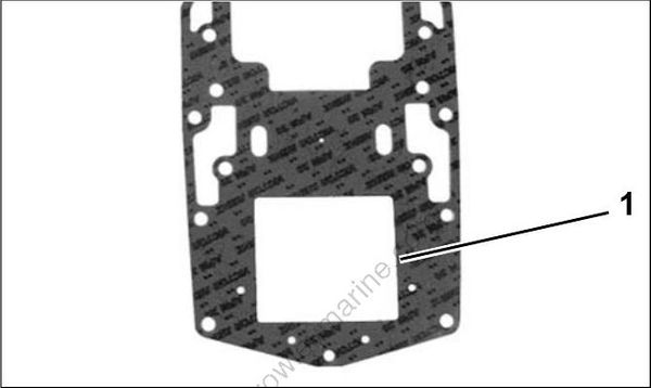
- Inner exhaust area
000661
Coat the driveshaft splines with Moly Lube. Do not apply lubricant to end of driveshaft.
Use Lifting Fixture, P/N 396748, and hoist to slowly lower power head onto exhaust housing. If necessary, rotate flywheel in a clockwise direction to align crankshaft and driveshaft splines.
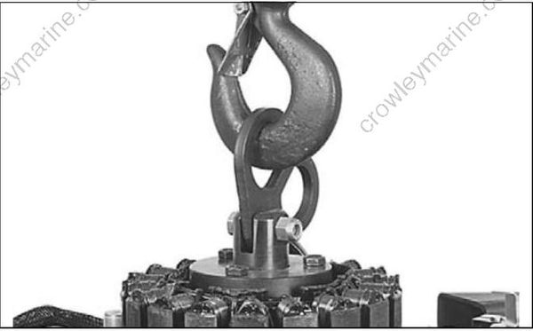
48758
Apply Gasket Sealing Compound to the threads of all power head screws. Loosely install all fasteners before tightening. Tighten the 3/8 in. diameter power head screws to a torque of 20 to 22 ft. lbs. (27 to 30 N·m) in the sequence shown. Tighten the 5/16 in. diameter power head screws to a torque of 144 to 168 in. lbs. (16.5 to 19 N·m) in the sequence shown.
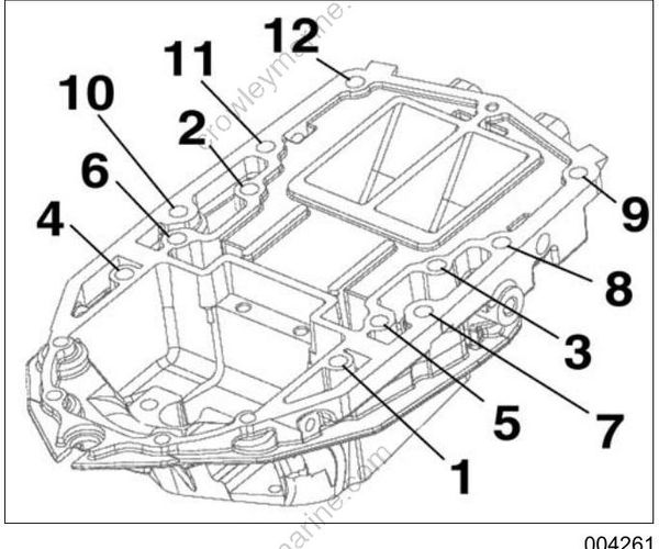
004261
IMPORTANT: Retighten power head mounting screws after outboard has been run at full operating temperature and allowed to cool.
Install two front and one rear power head nuts. Tighten nuts 144 to 168 in. lbs. (16.5 to 19 N·m).
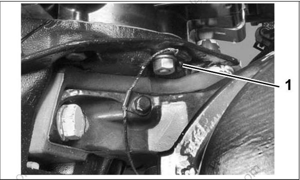
- Front power head nut (2)
004262
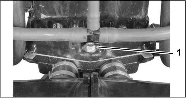
- Rear power head nut
004252
Place the shift rod in the shift rod lever. Install the retaining pin and washer. Tighten pin to a torque of 60 to 84 in. lbs. (7 to 9.5 N·m).
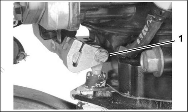
- Shift rod pin
004241
IMPORTANT: Make sure the gear case shifts solidly into both forward and reverse and that propeller shaft spins freely in neutral.
Install water hoses and exhaust back pressure hose.
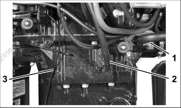
Port side
- Cooling hose (from exhaust plenum)
- Cooling hose (from vapor separator)
- Speedometer hose
008443
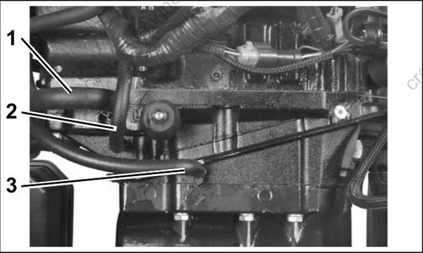
Starboard side
- Cooling hose (to exhaust plenum)
- Exhaust back pressure hose (to EMM)
- Cooling hose (from block) – 3.3 L models
005042
Route power trim harness through clamp and connect to engine harness.
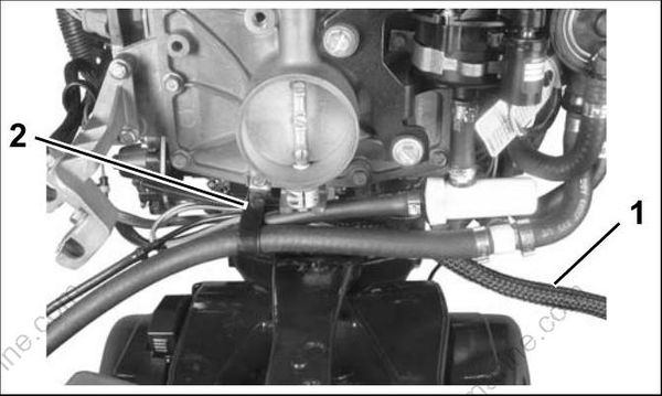
- Trim harness
- Clamp
006992
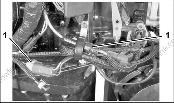
- Trim/tilt connectors
004251
Install flywheel. Refer to Flywheel Installation on p. 110.
Install air temperature sensor, air silencer, and fly wheel cover. Tighten flywheel cover screws to a torque of 30 to 42 in. lbs. (3.5 to 5 N·m).
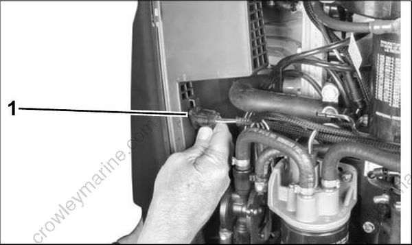
- Air temperature sensor
004219
Install the lower engine covers. Refer to LOWER COVER SERVICE on p. 51.
Pre-Service Adjustments
After installing a new or rebuilt power head, perform the following procedures before returning outboard to service:
• Adjust timing pointer.
• Index all spark plugs. Refer to Spark Plug Indexing on p. 40.
• Use Evinrude Diagnostics software to start power head break-in oiling. Refer to Power head Break-In on p. 67.
• Use Evinrude Diagnostics software to set TPS calibration. Refer to TPS CALIBRATION on p. 113.
• Use Evinrude Diagnostics software to make sure engine management software version and revision are current. Update as required.
• Prime fuel system.
• Prime oiling system. Refer to OIL SUPPLY PRIMING on p. 170.
• Use Evinrude Diagnostics software to check engine timing. Refer to TIMING ADJUSTMENTS on p. 112.
• Run outboard and check for water, fuel, or oil leaks.
• Make sure engine reaches correct operating temperature and does not overheat.
