

LUBRICATION
Temporarily cover the small holes on the front of M2-Type gearcases with waterproof tape to make sure enough water travels to the powerhead. Water can drain from auxiliary inlets, resulting in engine overheat.
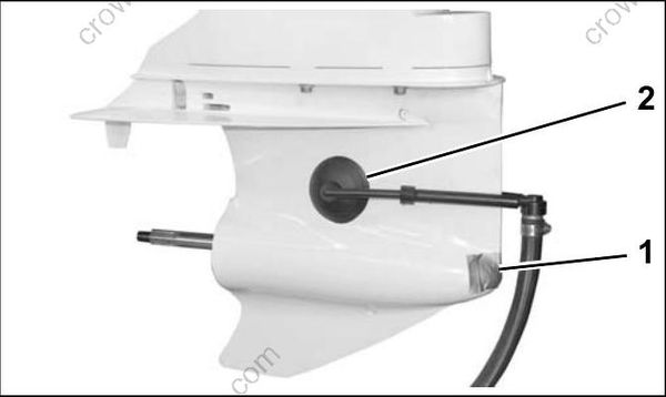
008358
M2-Type Gearcase
- Water-proof tape
- Flushing adapter
A steady stream of water should flow from the overboard indicator while the engine is running.
Monitor engine water pressure gauge when:
- Engine speed is above 3000 RPM
- Running engine on a dynamometer.
Refer to SERVICE SPECIFICATIONS on p. 10 for water pressure requirements.
Engine will overheat if normal water pressure is not maintained. Temporarily install an engine water pressure gauge if not equipped with one.
Be sure to remove waterproof tape from auxiliary water inlets.
Engine will overheat if auxiliary water inlets are restricted when outboard is back in service.
Steering System
Failure to regrease as recommended could result in steering system corrosion. Corrosion can affect steering effort, making operator control difficult.
Grease the stainless steel output end of the steering cable with Triple-Guard grease.
Use an appropriate cleaning solvent to remove corrosion and dirt from output end of cable prior to coating it with grease. Make sure wiper nut is installed and not damaged.
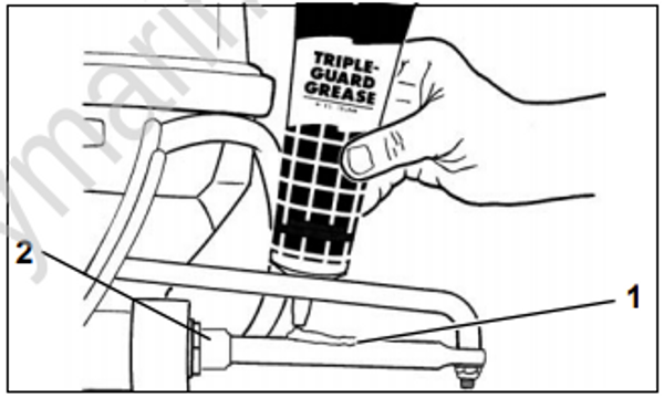
DR29546
- Steering cable
- Wiper nut
Tilt Tube
Lubricate the tilt tube grease fittings with TripleGuard grease.
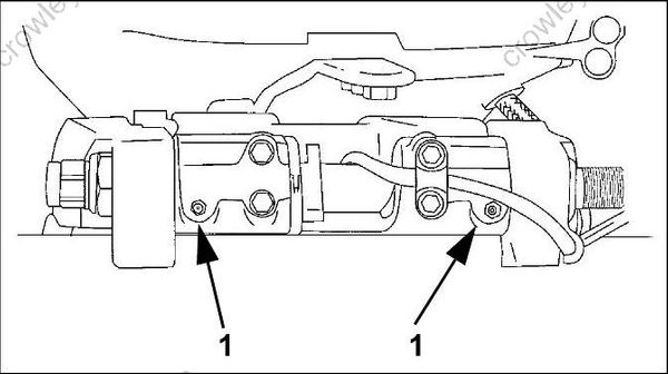
DR38798
- Tilt tube fittings
Swivel Bracket and Trailering Bracket
Lubricate the swivel bracket with Triple-Guard grease.
Apply grease until the grease begins to flow from the upper or lower swivel bracket areas.
Coat the pivot points of the trailering bracket with Triple-Guard grease.
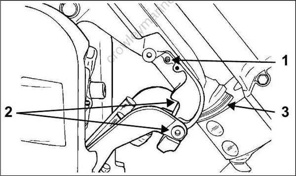
DR5073
- Grease fitting
- Pivot points
- Lower swivel bracket area
Throttle and Shift Linkage
Disconnect the battery cables at the battery.
Remove cable trunnion cover. Carefully, remove throttle and shift cables from trunnion block.
IMPORTANT: DO NOT disturb cable trunnion adjustments.
Shift remote control into FULL THROTTLE / REVERSE position to fully extend the plastic casing guides.
Apply Triple-Guard grease to:
Cable attachment pins of both the throttle and shift levers.
Inner casings of both the throttle and shift cables.
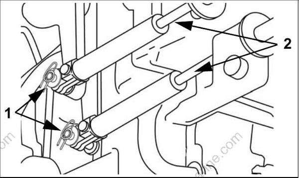
DRC6500GE
- Attachment pins, throttle and shift cables
- Inner casings, throttle and shift cables
Shift the remote control to the NEUTRAL/IDLE position.
Install control cables.
Check proper throttle and shift function.
Propeller Shaft
Debris from the water can become lodged around propeller shaft. Frequent inspection can minimize potential gearcase damage.
When servicing the propeller, always shift the outboard to NEUTRAL, turn the key switch OFF, and disconnect the battery cables at the battery.
Remove propeller. Refer to Propeller Hardware Installation on p. 266.
Inspect bushing and blade surfaces. Replace damaged or worn propellers.
Clean propeller shaft. Inspect propeller shaft seals. Replace damaged or worn seals.
Apply Triple-Guard grease to entire length of propeller shaft prior to installing propeller.
Reinstall propeller hardware and propeller.
Gearcase Lubricant
Draining
Gearcase lubricant may be under pressure and/or hot. If plug is removed from a recently operated outboard, take precautions to avoid injury
IMPORTANT: Always check the fill level of the gearcase lubricant at the upper plug before removing the lower, drain/fill plug. A tie strap can be used to check lubricant level.
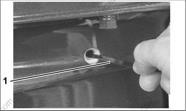
000072
- Tie strap
If lubricant level is low, refer to GEARCASE LEAK TEST on p. 267.
Remove the lubricant level plug, then the lubricant drain/fill plug, and drain the lube from the gearcase into a container.
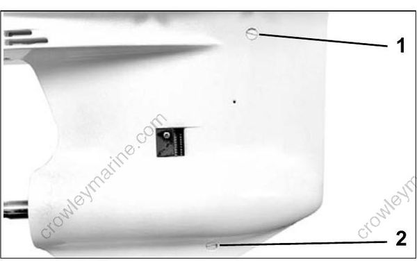
39514
- Lubricant level plug
- Lubricant drain/fill plug
Inspection
Inspect the lubricant and the magnets on the plugs for metal chips. The presence of metal fuzz can indicate normal wear of the gears, bearings, or shafts within the gearcase. Metal chips can indicate extensive internal damage.
Inspect the lubricant for water contamination. Water can make the lubricant milky in appearance. However, normal aeration can also cause the same appearance.
To check for water contamination, put lubricant into a glass container. Allow the oil to settle for a minimum of one hour to determine if there is an abnormal amount of water in the oil.
If water is present, refer to GEARCASE LEAK TEST on p. 267.
Overheated lubricant will have a black color and burned odor.
Internal gearcase inspection is recommended when lubricant is contaminated or shows signs of failure.
Filling
Refer to the INSPECTION AND MAINTENANCE SCHEDULE on p. 14 for service frequency and recommended lubricants.
Secure the gearcase in a vertical position.
Remove the lubricant level plug and the lubricant drain/fill plug.
Use Gearcase Filler, P/N 501882, to slowly fill the gearcase with HPF PRO lubricant through the drain/fill hole until it appears at the oil level hole.
IMPORTANT: Filling the gearcase too quickly can cause air pockets and the gearcase may not fill completely.
Clean plug seal area and install the lubricant level plug and new seal, then the lubricant drain/fill plug and new seal. Tighten plugs to a torque of 60 to 84 in. lbs. (7 to 9.5 N·m).
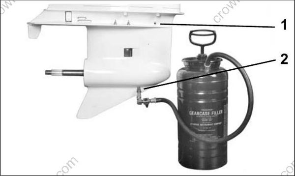
002386
- Lubricant level plug
- Lubricant drain/fill plug
IMPORTANT: The recommended gear lubricants are formulated for marine applications. Do not use automotive gear lubricants, engine oils, or any other oil or grease.
Trim and Tilt
Correct fluid level must be maintained to ensure operation of the impact protection built into the unit.
Check reservoir fluid level every three years or every 300 operating hours.
System capacity is approximately 21 fl. oz. (620 ml).
Tilt the outboard and engage the tilt support.
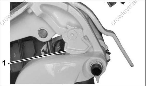
002279
- Tilt support bracket
Remove filler cap and check fluid level.
Three Ram System–Add Power Trim/Tilt Fluid or GM Dexron II, as needed, to bring level to the bottom of the fill plug threads.
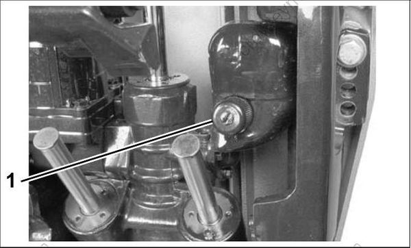
004277
Three Ram System, 115 - 200 HP
- Fill cap
- Single Ram System–Add Evinrude/Johnson Biodegradable TNT Fluid, as needed, to bring level to the bottom of the fill plug threads.
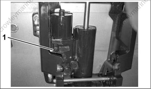
008017
Single Ram System, 115 - 130 HP
- Fill cap
Install the filler cap and tighten to a torque of 45 to 55 in. lbs. (5 to 6 N·m).
Disengage tilt support.
Cycle the unit at least five complete cycles to purge all air from the system. When cycling the unit, hold the trim switch ON an additional 5 to 10 seconds after the unit reaches the end of its travel before activating the switch in the opposite direction.
Spark Plugs
Spark plugs should be removed and examined periodically. Replace worn, fouled or damaged spark plugs.
Use only recommended spark plugs with the correct gap setting.
| Spark Plug, Champion |
|---|
| QC10WEP @ 0.028 ± 0.003 in. (0.71 mm) |
Remove spark plugs and inspect condition.
Set spark plug gap on new, replacement spark plugs.
Mark spark plugs for ground electrode orientation.
Apply Electrical Grease to the ribbed portion of the spark plug ceramic and to the opening of the spark plug cover to prevent corrosion.
Install spark plugs using “indexing” procedure.
Indexing
Spark plug indexing positions the ground electrode of the spark plug opposite the fuel injector nozzle.
Put an ink mark on the ceramic of the spark plug in line with the OPEN side of the ground electrode. This mark will be used to orient the spark plug with the OPEN side of the ground electrode facing the fuel injector.
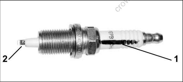
000758
- Ink mark
- Open side
