Battery Installation
IMPORTANT: MFE 55 models can be used to charge an accessory boat battery by installing a battery cable, P/N 584348, to the existing solenoid on the outboard. Also, electric start capability is available through the installation of Electric Start Kit, P/N 5005580.
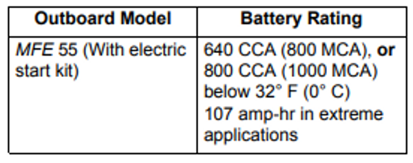
Each outboard requires its own starting battery. Select a battery that meets or exceeds the minimum requirements.
Battery Recommendations
Battery Location
Proper installation will prevent battery movement while underway.
- Secure all batteries in protected locations.
- Place battery as close to the outboard as possible.
- Battery location must provide access for periodic maintenance.
- Use battery mounting trays or battery boxes on all battery installations.
- Connections and terminals must be covered with an insulator.
- Battery connections must be clean and free from corrosion.
- Read and understand the safety information supplied with the battery before installation.
Battery Connections
Keep the battery connections clean, tight, and insulated to prevent their shorting or arcing and causing an explosion. If the battery mounting system does not cover the connections, install protective covers. Check often to see that connections stay clean and tight.
IMPORTANT: Connect the battery positive (+) cable to the battery positive (+) post FIRST. Connect the battery negative (–) cable to the battery negative (–) post LAST.
Install a starwasher on the threaded battery post. Stack cables from the outboard, then cables from accessories. Finish this connection with a hex nut.
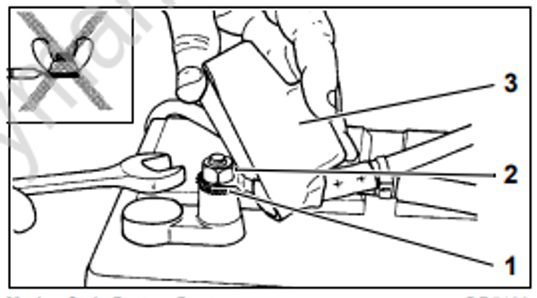
Do not use wing nuts to fasten ANY battery cables. Wing nuts can loosen and cause electrical system damage not covered under warranty
Tighten all connections securely. Apply TripleGuard grease to prevent corrosion.
Fuel System Requirements
Regulations and Guidelines
Vessel manufacturer, and/or installer of an EPA certified outboard, must meet minimum specifications for boat fuel systems established by:
- U.S. Environmental Protection Agency (EPA)
– 40 CFR 1045.112
– 40 CFR 1060 - U.S. Coast Guard (USCG)
– 33 CFR 183 - American Boat & Yacht Council (ABYC)
– Standard H-24
– Standard H-25.
Permanent Fuel Tanks
Permanent fuel tanks must be properly vented outside of the hull.
Remote fuel tank gas fills must be grounded.
Fuel tank pickups should include an anti-siphon valve to prevent fuel flow if a leak occurs in the fuel distribution system.
Portable Fuel Tanks
If engine is equipped with a quick-disconnect fuel hose, you MUST disconnect the fuel hose from the engine and the fuel tank to prevent fuel leaks:
• Whenever the engine is NOT being used
• Whenever the engine is being trailered
• Whenever the engine is in storage.
NOTE: A small amount of fuel may be released when the fuel connector is disonnected.
Store portable fuel tanks in well-ventilated areas, away from heat sources and open flames. Close the vent screw of the fuel tank cap, if equipped, to prevent escape of fuel or fuel vapors which could accidentally ignite. Do not allow disconnected fuel hoses to leak fuel.
Fuel Hose
All fuel hoses used for rigging outboards manufactured after January 1, 2009 must meet EPA permeation requirements for evaporative emissions.
- Use SAE J30R9, or USCG Type B1-15, fuel hose in motor well areas.
- Use USCG Type A1-15 fuel hose between permanent fuel tanks and motor well fittings in inaccessible routings.
- Compliant hoses are labeled with the applicable specification.
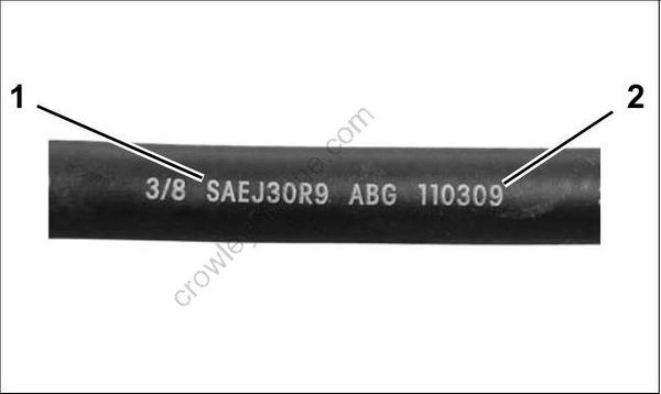
- Specification
- Date code
Permanently installed fuel hoses should be as short and horizontal as possible.
Use corrosion-resistant metal clamps on permanently installed fuel hoses.
Multi-outboard applications require separate fuel tank pickups and hoses. (A fuel selector switch may be used for “kicker” motors as long as it has enough flow capacity for the larger outboard.)
Use only fuel lines (or copper tubing) that meet the Fuel Flow Requirements for the outboard.
Fuel System Primer
Outboards require a priming system to refill the fuel system after periods of non-use. The most common priming system is a primer bulb in the fuel supply hose.
Install the primer bulb as follows:
- The primer bulb must meet the same Fuel Flow Requirements as the fuel hose.
- The primer bulb should be easily accessible.
- The arrow on the primer bulb must point in the direction of fuel flow.
- The fuel supply hose must allow the primer bulb to be held with the arrow pointing up during priming.
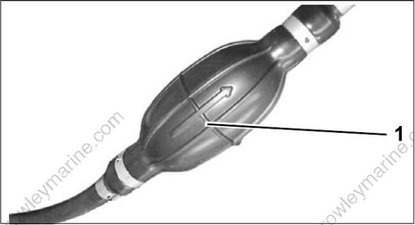
- Arrow indicates direction of fuel flow
An alternative to a primer bulb is a U.S. Coast Guard approved marine primer pump. Electric primer pumps offer the convenience of outboard priming from a dash-mounted momentary switch.
Fuel Filters
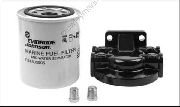
Boat-mounted fuel filters and water-separating fuel filter assemblies must meet the required fuel flow and filter specification. Refer to Fuel Flow
Requirements.
The filter must be mounted to a rigid surface above the full level of the fuel tank and accessible for servicing.
Fuel Filter Assembly, P/N 174176, meets all requirements for a water-separating fuel filter
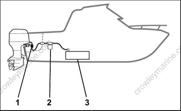
Typical Fuel Supply Configuration
- Primer bulb
- Water separating fuel filter
- Anti-siphon valve, in fuel pick-up of tank
Avoid using in-line fuel filters external to the outboard. The filter area and flow characteristics may not be adequate for high horsepower outboards.
Fuel Flow Requirements
| Component | MFE 55 Models |
|---|---|
| Fuel tank pickup tube | 5/16 in. (7.9 mm) min. I.D. |
| Fuel fittings | 1/4 in. (6.4 mm) min. I.D. |
| Fuel supply hoses | 5/16 in. (7.9 mm) min. I.D. |
| Fuel tank pickup screen | 100 mesh, 304 grade stainless steel wire, 0.0045 in. wire diameter,1 in. (25 mm) long |
| Antisiphon valve | 2.5 in. (63.5 mm) Hg maximum pressure drop at 20 gph (76 l/hr) flow |
| Remote fuel filter | 0.4 in. Hg maximum pressure drop at 20 gph (76 l/hr) flow, 150 in.2 (1290 cm2) of filter area |
| Maximum fuel pump lift height | Fuel pump should not be located more than 30 in. (76.2 cm) above bottom of fuel tank |
Oetiker Clamp Servicing
Clamp Identification
Use Oetiker clamps for making hose connections. These clamps provide corrosion resistance, minimize the potential for abrasion of rigging components, and provide solid, permanent connections.
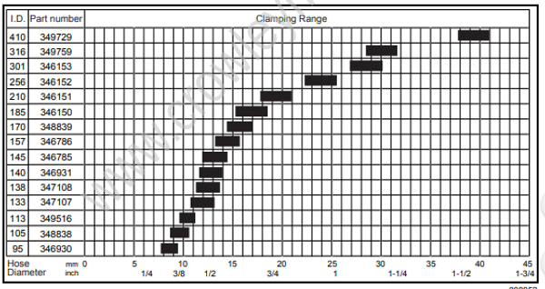
The selection and installation of an Oetiker clamp is essential in the proper sealing of hose connections. The clamp identification numbers appear on the side of the clamp, near the top of the ear. Refer to Clamp Selection chart for dimensions.
DO NOT re-use Oetiker clamps. Fuel leakage could contribute to a fire or explosion.
Clamp Selection
To select the correct size Oetiker clamp, measure the outside diameter of the hose when installed on the fitting.
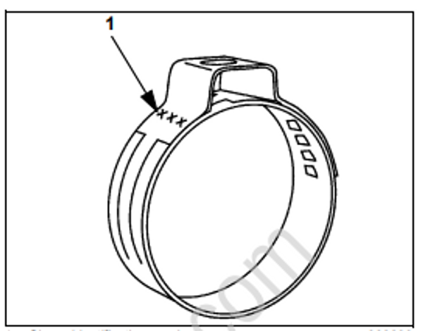
- Clamp identification numbers
Chose a clamp so that the outside diameter of the hose is approximately in the middle of the clamping range of the clamp.
Clamp Installation
A constant stress should be applied to close the ear clamps. This method ensures a positive stress on the hose and does not result in excessive compression or expansion of the band material.
IMPORTANT: Use only Oetiker recommended tools to close Oetiker stepless clamps.
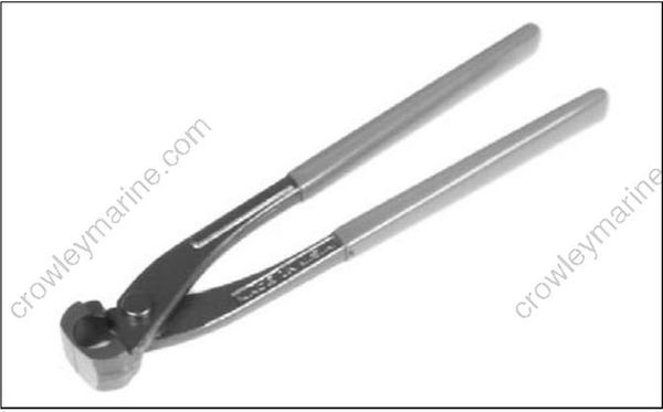
Oetiker pincers, P/N 350860, are available in the Evinrude/Johnson Genuine Parts and Accessories Catalog.
- Position correct size clamp over hose.
- Install hose on fitting.
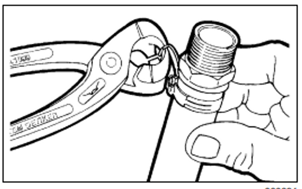
- Close clamp ear fully with Oetiker pincers (pliers).
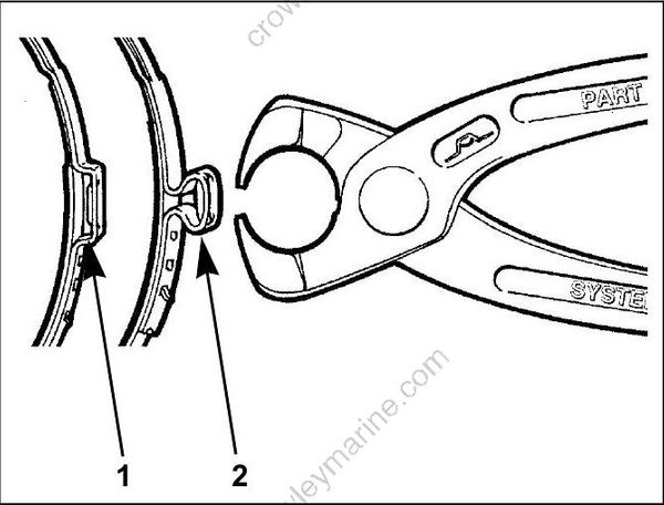
- Open clamp
- Closed clamp
Clamp Removal
Method 1: Position Oetiker pincers across clamp ear and cut clamp.
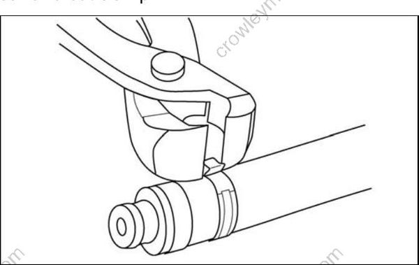
Method 2: Lift end of stepless clamp with screwdriver
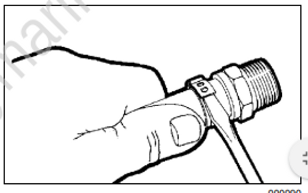
Method 3: Use Oetiker pincers (pliers) to grip clamp. Pull clamp off of connection and discard.