PROPELLER SERVICE, MRL MODELS
Inspection
Carefully examine propeller and outboard for the following:
- Damaged blades and signs of propeller cavita tion (burned paint, etc.)
- Spun or overheated inner hub
- Worn or twisted splines and inadequate lubri cant
- Damaged or missing converging ring (if applica ble)
- Damage to outer hub area
- Worn, missing, or incorrect thrust washer and spacer
- Correct size and style
- Check for bent or damaged propeller shaft and twisted splines.
Refer to Propeller Hardware Installation on p. 42.
When servicing the propeller, always shift the outboard to NEUTRAL, turn the key switch OFF, and disconnect the battery positive (+) cable so the outboard cannot be started accidentally.
IMPELLER SERVICE, MJRL MODELS
Inspection
To prevent accidental starting while servicing, twist and remove all spark plug leads.
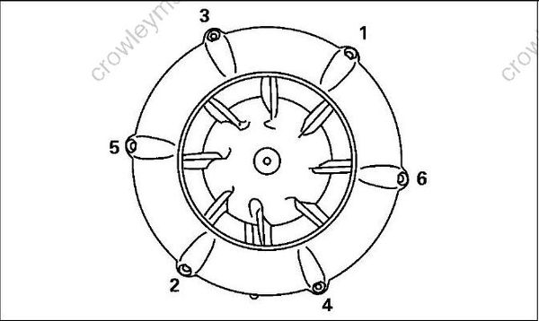
Use a 3/16 Ballhex driver to remove the six impeller housing screws. Remove the impeller housing.
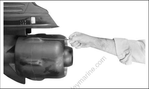
Insert a 1/8 in. shim between the impeller and the impeller housing. If the shim moves freely for the entire length of the impeller blade tip on any of the blades, the impeller is worn and must be replaced.
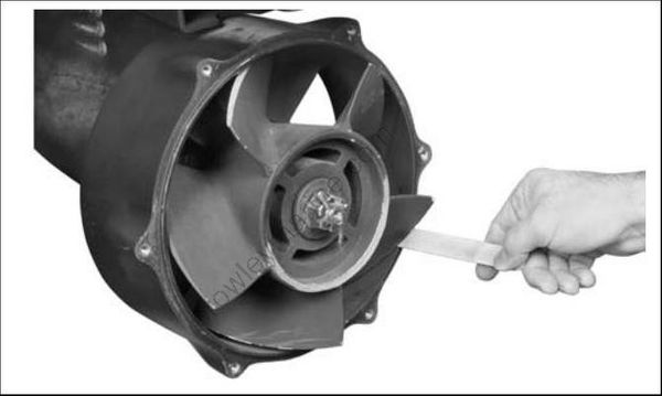
Rotate the impeller 30° and repeat the inspection.
Removal
Wedge a block of wood between impeller blade and starboard side of the gearcase. Remove the cotter pin and loosen the impeller nut.
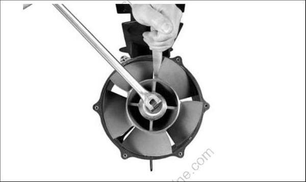
Remove the nut, spacer, impeller, and thrust bushing.
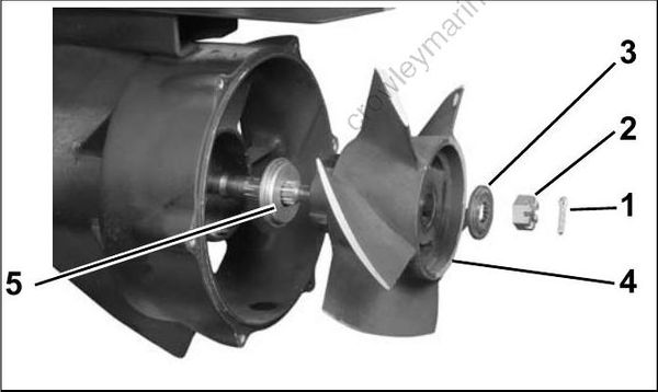
- Cotter pin
- Impeller nut
- Spacer
- Impeller
- Thrust bushing
Installation
Apply a small amount of Triple-Guard grease to the impeller shaft splines. Place the thrust bushing in the impeller and then slide the assembly onto the impeller shaft.
Install the spacer on splines of the impeller shaft.
Wedge a block of wood between impeller blade and port side of the gearcase. Install and tighten the impeller nut to a torque of 120 to 140 in. lbs. (14 to 16 N·m).
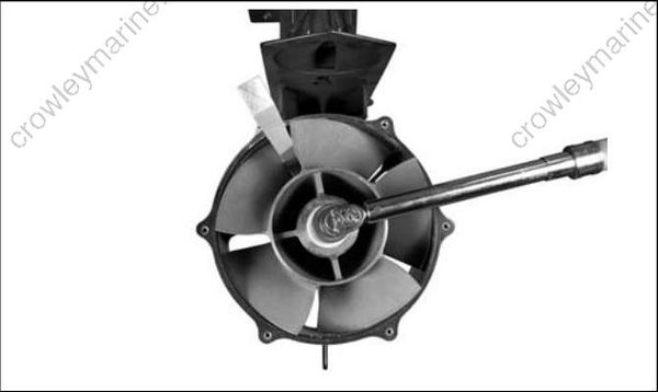
If cotter pin holes in the impeller nut and impeller shaft are not aligned, continue to tighten the nut until they are in line. Do not loosen.
Insert a new cotter pin through the impeller nut and shaft. Bend its ends over the nut to secure the assembly.
Install the impeller housing, and following
sequence shown, tighten screws in stages to a
torque of 70 to 100 in. lbs. (8 to 12 N·m).