

HP Oil System
Use the XD100 Outboard Oil Decal, P/N 352369, to accurately inform the boat operator of the XD100 outboard oil requirement.
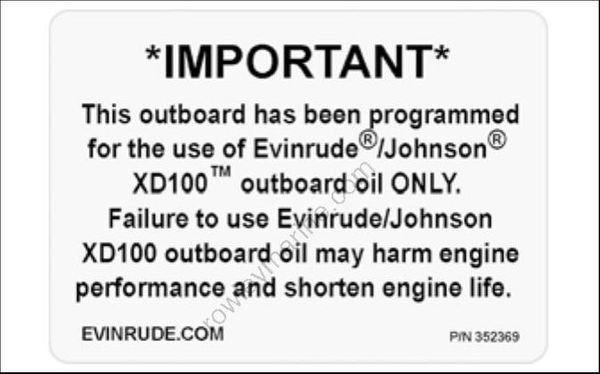
XD100 Outboard Oil Decal
Install this decal in one or more of the highly visible recommended locations to alert the outboard operator(s).
Recommended Locations:
- Dashboard/deck of boat, adjacent to key switch
- Deck of boat, adjacent to the remote oil fill
- Deck of boat, adjacent to oil tank assembly
- Oil tank cover
- Cover of oil tank compartment
- Attach to oil tank or oil fill cap
IMPORTANT: Make sure the Evinrude E-TEC engine label and boat decal match EMM programming.
Break-in Oiling
The Break-in OIL setting doubles the oiling ratio for the first two hours of operation, above 2000 RPM. See Oil Control on p. 109.
OILING SYSTEM TESTS
IMPORTANT: Always perform visual inspections to identify oiling system leaks. Make sure the oil tank is filled and oil supply is not contaminated.
Oil Injection Pump Static Test
IMPORTANT: Static tests are performed with the outboard not running.
Use the Evinrude Diagnostics Software program to activate Oil Injector test. This initiates the EMM control function for the oil injection pump.
Oil injection pump should activate with key switch in the ON position.
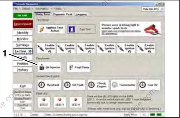
Static Tests Screen
- Oil injector test button
The EMM provides ground to pin 2 (blue wire) of oil injection pump electrical connector. Refer to Oil Injection Pump Voltage Test on p. 208.
Oil Injection Pump Voltage Test
Acceptable voltage readings:
- Key switch ON: approximately 30 V
- Outboard running: 55 V
STEP 1
Check voltage at pin 1 (white/red wire) of oil injection pump electrical connector with key switch ON.
Results:
• Approximately 30 V is acceptable with outboard not running. See Oil Injection Pump Circuit Resistance Test on p. 209.
• No voltage reading, proceed to STEP 2.
STEP 2
Run outboard. Check system voltage using diagnostic software program. The alternator/system output wires (white/red) are terminals 19 and 29 of the EMM J2 connector. If needed, use Electrical Test Probe Kit, P/N 342677, and a multimeter set to read 55 VDC to check engine harness voltage readings.
Results:
- Proper voltage reading, inspect connections and wiring. Replace faulty wire harness or connector.
- No or low voltage, check connections from EMM and stator to engine wire harness. Repair faulty connection or refer to STATOR TESTS on p. 141 for testing procedures.
STEP 3
Use Electrical Test Probe Kit, P/N 342677, and a multimeter set to read 55 VDC. Check voltage at pin 2 (blue wire) of oil injection pump connector. Key switch must be ON.
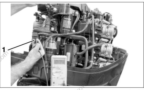
- Oil injection pump connector (pin 2)
Results:
- Approximately 30 V is acceptable, leave adapter connected, proceed to STEP 4.
- No voltage, refer to Oil Injection Pump Circuit Resistance Test on p. 209.
STEP 4
Activate oil injector using the Evinrude Diagnostics Software program. Monitor the voltage on oil injector pump circuit at pin 2 of oil injection pump connector.
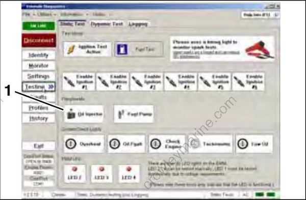
Static Tests Screen
- Oil injector test button
Oil Injection Pump Circuit Resistance Test
The oil injection pump circuit includes the engine wire harness, the injection pump winding and connector, and the oil injection control circuit of the EMM.
Disconnect the battery cables at the battery.
Use Electrical Test Probe Kit, P/N 342677, to make a connection to pin 23 of the EMM J1-B connector.
Calibrate ohmmeter to the LOW OHMS scale and measure the resistance between pin 23 of the EMM J1-B connector and pin 1 of oil injection pump connector.
| Oil Injection Pump Circuit Resistance |
|---|
| 2 to 3 Ω |
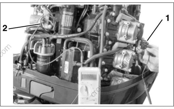
- EMM J1-B connector (pin 23)
- Oil injection pump connector (pin 1)
Results:
- An infinite reading (∞) indicates an open circuit. Isolate the faulty wiring, connection, or injection pump winding. Repair faulty wiring or replace faulty component and retest.
- For a higher than expected reading, test resistance of the injection pump. If injection pump resistance reading is approximately 2-3 Ω, injection pump winding is good. Isolate faulty component. Repair faulty wiring or replace faulty component and retest.
Oil Supply Vacuum Test
Wear safety glasses to avoid personal injury, and set compressed air pressure to less than 25 psi (172 kPa).
Remove the oil pick-up assembly from the oil tank.
Carefully remove the pickup filter and flush with a mild solvent to remove any contamination. Rein stall filter.
Carefully remove the oil hose from the oil pickup and remove the oil supply hose from the oil injection pump.
Use low pressure air to purge oil from hose.
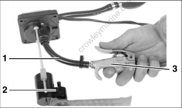
- Oil hose
- Oil pickup
- Low pressure air
Use Plug/Holder, P/N 329661, and clamp to plug the pickup end of the hose.
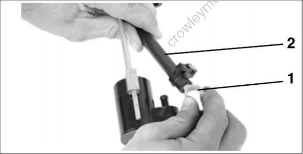
- Plug/holder
- Oil hose
Attach a vacuum tester to the outboard side of oil supply hose and draw 7 in. Hg (24 kPa) vacuum on the hose for at least five minutes. Repair or replace any leaking components. Reinstall the oil hose.
Check height of pickup assembly.
| Pickup Assembly Height |
|---|
| 1.8 gallon tank 6.84 to 6.96 in. (174 to 177 mm) |
| 3.0 gallon tank 8.74 to 8.86 in. (222 to 225 mm) |
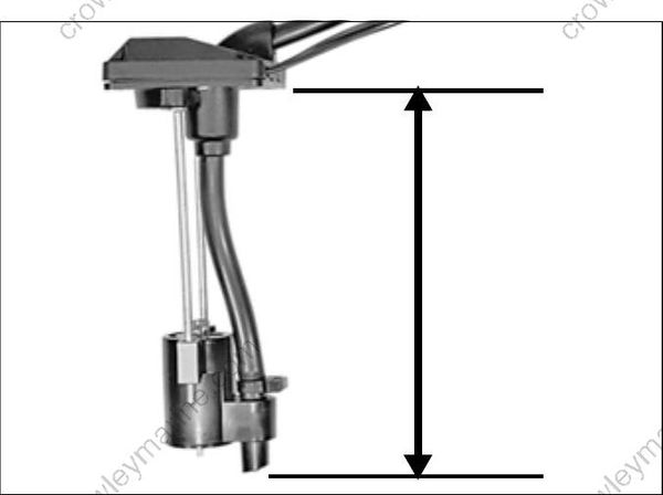
Height of Oil Pickup Assembly
Position a new seal on oil tank and reinstall pickup with filter into oil tank. Install and tighten screws.
Oil Injection Pump Function Test
This test may be performed in two different ways:
Running Test
Remove oil distribution hose from fitting at cylinder block. Start and run the outboard at IDLE speed and observe oil flow. Confirm that a small amount of oil is discharged while injection pump is activated.
Static Test
Remove oil distribution hose from fitting at crankcase. Squeeze oil supply primer bulb to provide oil to injection pump.
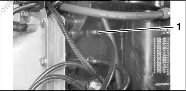
TYPICAL
- Fitting at cylinder bloc
Use the oil injector test of the Evinrude Diagnostics Software program to activate injector. Confirm that a small amount of oil is discharged while injection pump is activated.
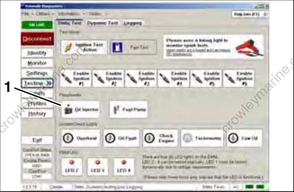
Static Tests Screen
- Oil injector test button
Results:
• Oil flows from distribution hose, compare to oil flow at other distribution hoses.
• No oil discharge, compare to oil flow at other distribution hoses. If one or more hoses fail to discharge oil, check for a kinked or restricted hose before replacing the oil injection pump assembly.
Oil Injection Fittings Flow Test
To prevent accidental starting while servicing, disconnect battery cables at the battery.
Confirm that the oil injection fittings of the crankcase allow fluid to move.
Remove oil distribution hose from fitting. Connect 1/8 in. I.D. (3 mm) clear vinyl tubing to the fitting. Use a syringe filled with isopropyl alcohol to force fluid through the fitting.
LOW OIL Sending Unit Test
Remove the oil from the oil tank, and turn the key switch ON. The LOW OIL light of the System-Check gauge should activate. Once the warning has been verified, turn the key switch ON and refill the oil tank. Confirm that the LOW OIL warning stops as the oil level exceeds one-quarter of oil tank’s capacity.
OIL COMPONENT SERVICING
To prevent accidental starting while servicing, disconnect battery cables at the battery.
IMPORTANT: Access to certain oil distribution hoses requires removal of various engine components. Refer to service information in the various sections of this manual for additional information related to the removal and installation of specific components. DO NOT disassemble or replace any oiling system components until you are familiar with the entire OILING SYSTEM section.
Oil Distribution Hoses
The oil distribution hoses to each cylinder MUST be the same length. DO NOT alter the length of any hoses.
| Oil Distribution Hose Length |
|---|
| Manifold-to-cylinder block fitting 12 in. (305 mm) |
| Manifold-to-idle oil circuit fitting 28 in. (711 mm) |
Removal
The oil distribution manifold has oil hose retainer mechanisms incorporated into the design.
Use a pen or marker to mark the position of the oil hose relative to the retaining mechanism.
Release the hose by depressing the outer ring of the hose retaining mechanism.
