

OUTBOARD RIGGING
To prevent accidental starting while servicing, disconnect the battery cables at the battery. Twist and remove all spark plug leads.
Cable, Hose, and Wire Routing
Remove two screws and bracket that fasten the grommet to lower motor cover.
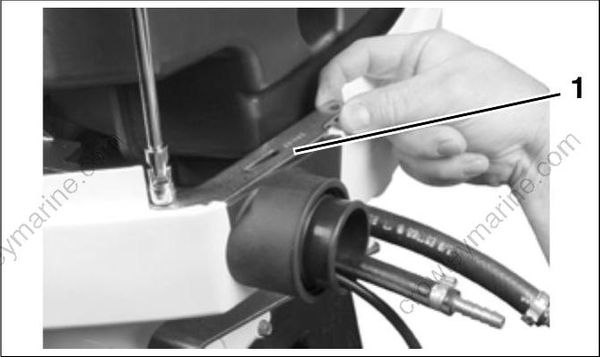
- Grommet retaining bracket
Route all hoses, control cables, and wiring through a protective sleeve or conduit into the boat and through the grommet.
The fuel hose may be routed through the protective sleeve or through an alternate hole in the lower motor cover grommet.
To route the fuel hose outside the sleeve, trim the material covering the alternate fuel hose slot in the grommet.
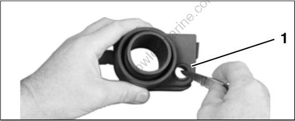
- Alternate fuel hose location
Refer to the following diagram to ensure proper positioning of rigging components in grommet.
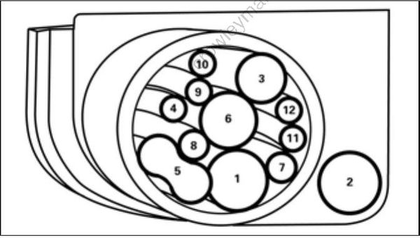
- Fuel supply hose
- Fuel supply hose--alternate location
- Oil supply hose
- Oil tank sending unit harness
- Battery cables
- Main wire harness (MWS)
- Shift cable
- Throttle cable
- Accessory charge wires
- CANbus harness
- Water pressure hose
- Speedometer hose

- Alternate fuel hose location
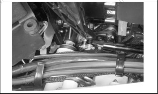
The main wiring harness, battery cables, oil tank sending unit harness, and any CANbus cables should be routed along the same path to the starboard side of the powerhead. Secure all cables with clamps.
Control Cable Installation
Remove remote control cable trunnion covers and cable attachment hardware.

- Trunnion covers
Cable Retainer Clip Installation
When installing retainer clips on control arm link age pins, clips should be locked and must not be bent or deformed.
For proper installation, review the following steps:
- Place washer on pin.
- Position retainer clip with straight section on the bottom and angled section on the top.
- Use long noses pliers to insert straight section of clip into linkage pin hole.
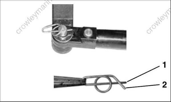
- Straight section
- Angled section
- Push the clip towards the hole while lifting on the curved end with the pliers.
- Be sure retainer clip fully engages the pin.
- Lock the retainer by moving the angled section behind the straight section.
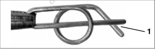
Locked Retainer Clip
- Angled section behind straight section
Shift Cable Installation and Adjustment
Position the shift cable on the shift lever pin and install the washer and retainer clip.
IMPORTANT: Do not bend or deform clip.
Confirm that the remote control, gearcase, shift linkage, and shift cable are in NEUTRAL.
Hold the shift linkage in NEUTRAL and grab the shift cable firmly.
Push and pull on the shift cable and observe the cable slack. Position the casing guide in the center of the slack.
Adjust shift cable trunnion to align with center of the trunnion block. Place cable trunnion in trunnion block.
Reinstall trunnion cover and screw. Tighten retaining screw to a torque of 60 to 80 in. lbs. (7 to 9 N·m).
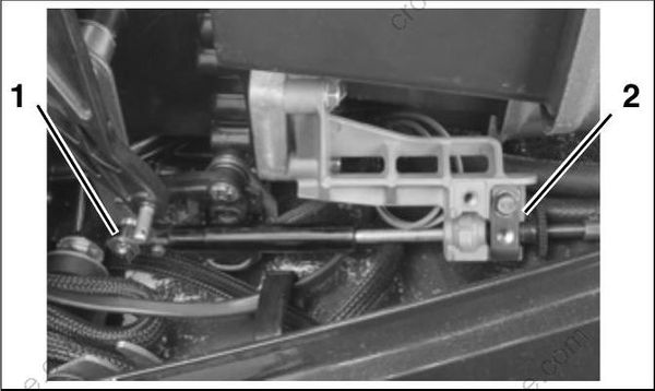
- Shift cable retainer clip and washer
- Shift cable trunnion
Throttle Cable Installation and Adjustment
Rotate the propeller shaft and shift control lever to FORWARD, then pull control lever half-way back to NEUTRAL.
Position throttle cable on throttle lever pin and install washer and retainer clip.
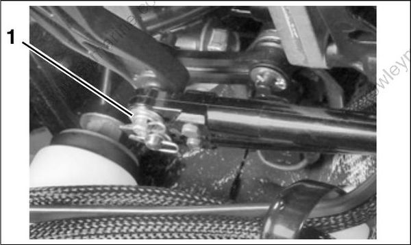
- Throttle cable retainer clip and washer
With throttle cable attached to the throttle linkage, pull cable to remove slack and ensure that idle stop of the throttle linkage is against the crankcase.
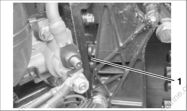
- Throttle linkage, idle stop against crankcase
Adjust the throttle cable trunnion to align with the trunnion block. Place the cable trunnion in the trunnion block.
IMPORTANT: DO NOT pre-load throttle cable. Make sure that the idle stop on the throttle linkage lightly contacts the crankcase when the remote control is in the IDLE position.
Reinstall the trunnion cover and screw. Tighten the retaining screw to a torque of 60 to 80 in. lbs. (7 to 9 N·m).
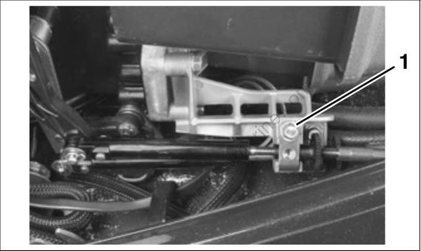
- Trunnion cover and screw, throttle cable
Electrical Harness Connections
Remove harness connector cover.
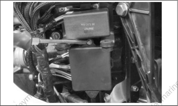
Before installing electrical connectors, check that the seal is in place. Clean off any dirt from connectors. Apply a light coat of Electrical Grease™ to the seal.

- Seal
Connect outboard main wire harness to boat main wire harness. Secure connectors in bracket. Refer to the diagram inside of the electrical cover.
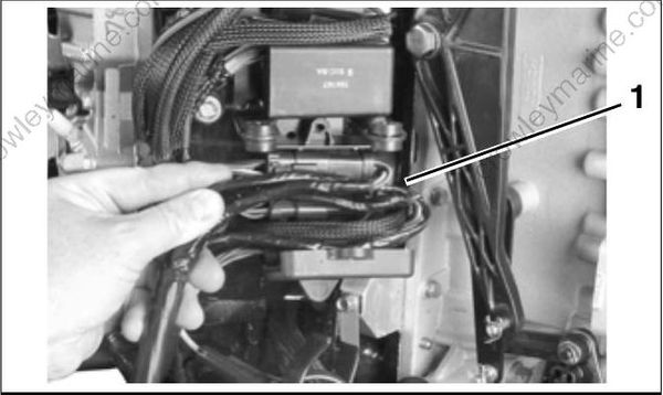
- Harness connections
Replace harness connector cover.
Install battery cables on starter solenoid and main ground stud.
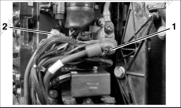
- Positive (+) battery connection
- Ground (–) connection
Water Pressure Gauge
If a mechanical water pressure gauge is used, install the water pressure hose fitting in the cylinder block. Use Pipe Sealant with Teflon, P/N 910048, on the threads of the hose fitting. Refer to installation instructions supplied with gauge.
Route the water pressure hose around the star board side of the powerhead along the same path as the battery cables.
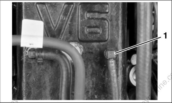
- Water pressure hose fitting
IMPORTANT: After installation, make sure there is enough clearance for all cables to avoid binding or chafing through all engine steering and tilting angles.
CANbus Connections
If the outboard will be used with an I-Command† system, or other NMEA 2000† compliant CANbus instruments, the following connections will supply information to the network:
Use a CANbus Ignition Harness, in place of the standard MWS harness, to connect the outboard to the key switch and trim/tilt control. Seal unused SystemCheck connector with 6-Pin Connector Seal, P/N 586076.
Connect the EMM CANbus connector to the boat CANbus network. Connect the purple wire from the CANbus Ignition Harness to the CANbus Network Harness. This connection supplies power to the network when the keyswitch is on.
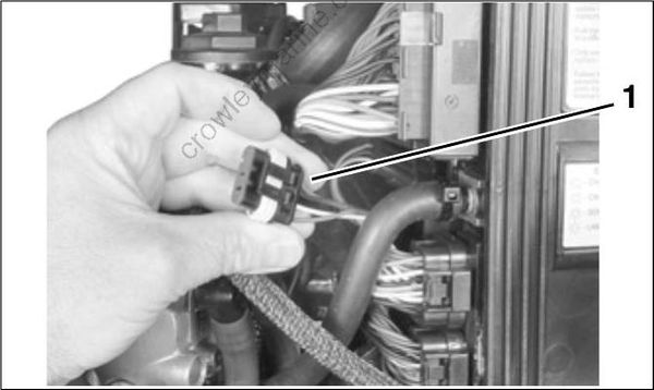
- EMM CANbus connector
Route the harness around the starboard side of the powerhead along the same path as the battery cables.
If a CANbus water pressure gauge is used, install Water Pressure Transducer Kit, P/N 5006214, in the cylinder block.
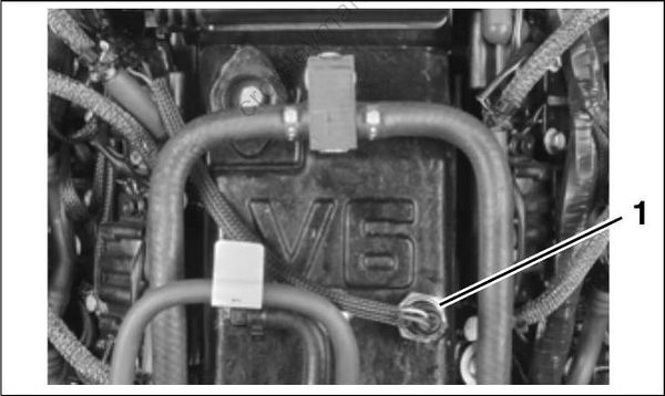
- Water pressure transducer
install the transducer lead in the engine wiring harness connector.

- Water pressure transducer lead
- Engine harness connector
- Cap
If a CANbus oil level gauge is used, an optional CANbus oil level sender must be installed in the oil tank. Connect the oil level sensor harness to the boat CANbus network.
Use the Evinrude Diagnostics Software program to activate CANbus control functions in the EMM. From the Settings screen, select Engine Options.

Engine options screen
- Trim gauge calibration
- Multi-engine setup
- Water pressure gauge setup
