

FUEL SYSTEM
Disconnect fuel manifold fittings from fuel injector ports.
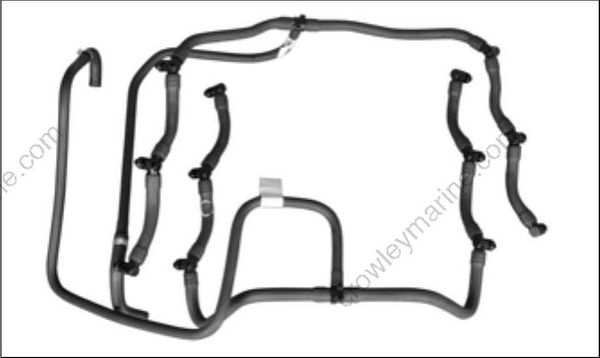
Remove any tie straps used to secure manifold(s) in place, then remove the manifold assembly(s).
Installation
Installation is essentially the reverse of removal. Pay close attention when performing the following additional tasks.
Install air silencer and connect battery cables.
Start outboard briefly to pressurize fuel system. Turn outboard OFF and inspect all fuel system components for leaks. Repair any fuel leaks.
INTAKE MANIFOLD
Removal
Remove oil/fuel pump bracket.
Disconnect throttle linkage. Remove throttle body screws and throttle body assembly.
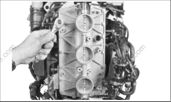
Remove gasket from throttle body.
Remove screws and reed plate assembly from the cylinder/crankcase assembly.
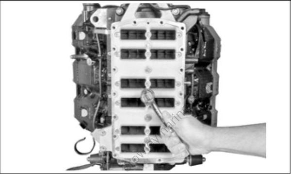
Disassembly
Visually inspect reed valve assemblies. For disassembly of the reed valve assembly, see Inspection on p. 192.
All reed plate assembly and reed valve assemblies must be cleaned prior to reassembly. DO NOT use strong carburetor cleaner or the hot soaking tank method for cleaning.
Remove the reed valve retainer screws and remove the assembly.
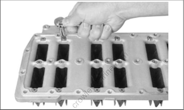
Use caution to prevent damaging reed valve assemblies.
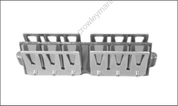
Inspection
DO NOT disassemble reed valve assemblies unless reed plate seats, reed valves, or reed stops are damaged, corroded, or contaminated with debris. Damaged reed plates are not serviceable and are replaced as an assembly.
Inspect the intake manifold. All gasket surfaces must be cleaned, smooth, and free of nicks. Use a machinist’s straight-edge to check flatness in all directions. Surface must be flat ± 0.004 in. (0.10 mm).
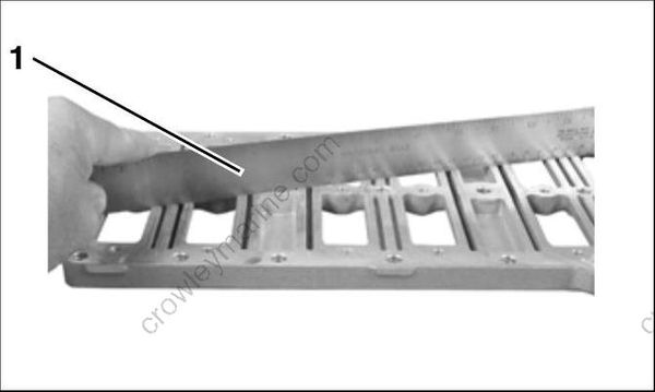
- Straight-edge
Inspect the leaf plate assemblies for damage or contamination:
- Leaf plates must not be distorted.
- Leaf valve must not be cracked or chipped.
- Leaf plate stops must not be distorted or loose.
- Leaf plate assemblies must be clean.
Assembly
Remove old adhesive from reed valve retaining screws.
Prime the threads with Locquic Primer and let dry. Apply Nut Lock_ to threads. Position reed valve on reed plate and install screws. Final torque is 30 to 42 in. lbs. (3 to 5 N-m).
Installation
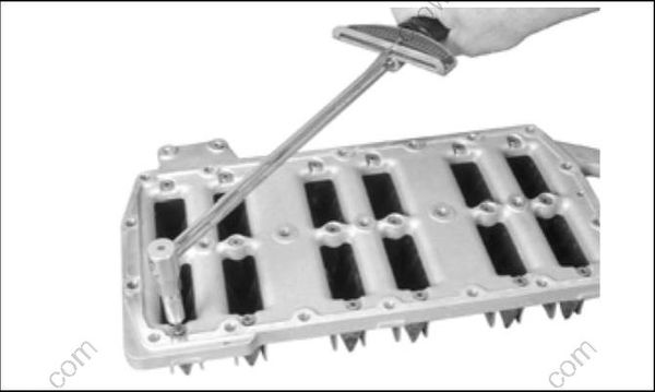
Position reed plate assembly on cylinder/crankcase.
Apply Nut Lock to screws. Install all screws.
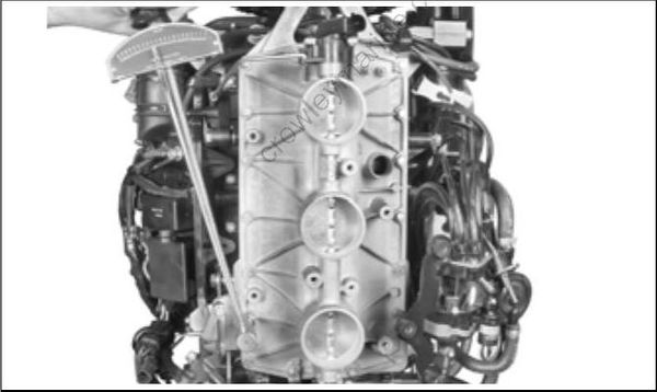
Tighten the center screws first and expand outward. Tighten in stages. Final torque is 96 to 120 in. lbs. (11 to 13.5 N-m).
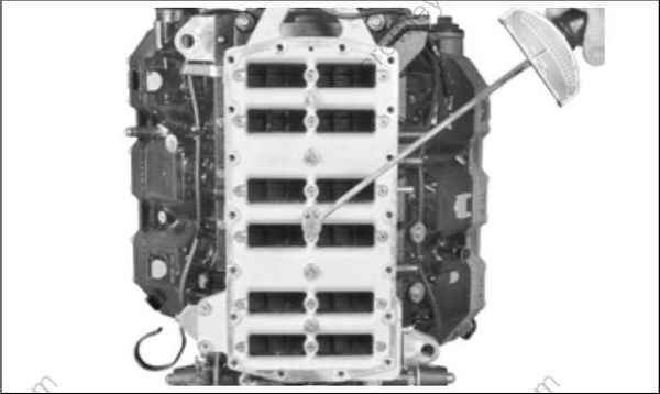
Position gasket on throttle body. Install throttle body on reed plate and install screws.
Tighten the center screws first and expand outward. Final torque is 96 to 120 in. lbs. (11 to 13.5 N-m).
Install vapor separator vent hose and oil recirculation hose. Secure with tie straps.
Connect throttle linkage and electrical connectors.
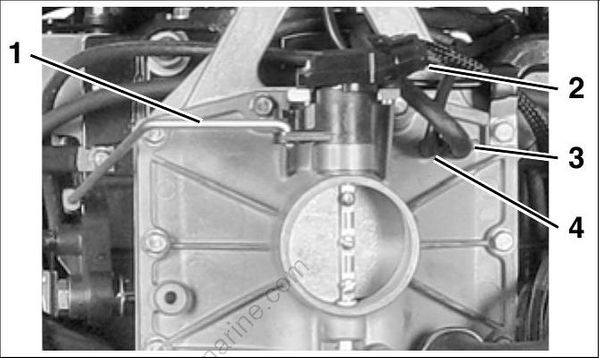
- Throttle linkage
- TPS electrical connector
- Vapor separator vent hose
- Oil recirculation hose
DO NOT lubricate TPS to throttle shaft surface.
Install oil/fuel pump bracket. Tighten screws 30 to 42 in. lbs. (3.5 to 5 N-m). Position clamps as shown.
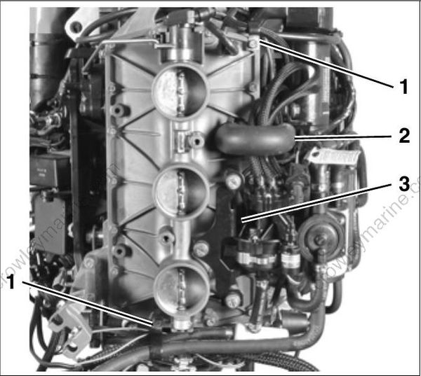
- Clamps
- Idle air hose
- Oil/fuel pump bracket
