

DIRECT INJECTION ELECTRICAL CIRCUITS
The outboard’s 55 V alternator circuit supplies the injectors with the necessary current. Unique circuits from the EMM distribute this current to the specific injector.
The EMM controls injector operation by rapidly connecting and disconnecting one side of each component’s internal coil to ground. Current must flow from the EMM to the injectors, through the winding of the component, back to the EMM, and through the EMM to ground. The injector’s internal coil provides approximately 3 ohms of resistance in the injector circuit.
Requirements for injector activation:
- 55 V system voltage from the EMM and through the individual circuits; and
- Switched ground connection provided by the EMM.
System voltage (55 V) output is produced by stator input to EMM and rectifier circuits of EMM.
Refer to FUEL DELIVERY on p. 131 for additional test procedures.
Injector / Circulation Pump Circuits Diagram
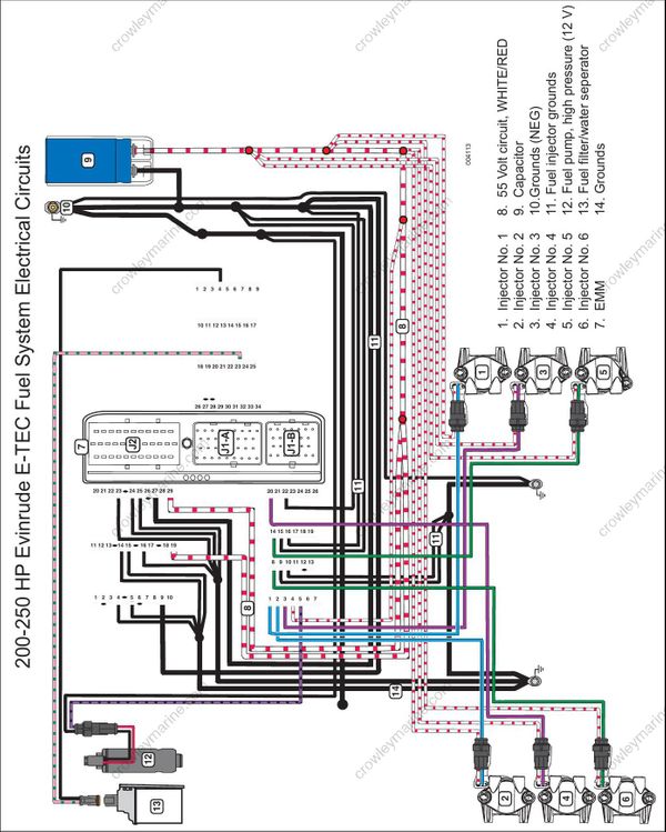
- Injector No. 1
- Injector No. 2
- Injector No. 3
- Injector No. 4
- Injector No. 5
- Injector No. 6
- EMM
- 55 Volt circuit, WHITE/RED
- Capacitor
- Grounds (NEG)
- Fuel injector grounds
- Fuel pump, high pressure (12 V)
- Fuel filter/water seperator
- Grounds
