

Cylinder Block / Cylinder Head cooling
Cylinder Block / Cylinder Head Cooling
The flow of water through the cylinder block and cylinder heads is controlled by two thermostats and one external pressure valve. The pressure valve is connected by hoses to the top of each cylinder head.
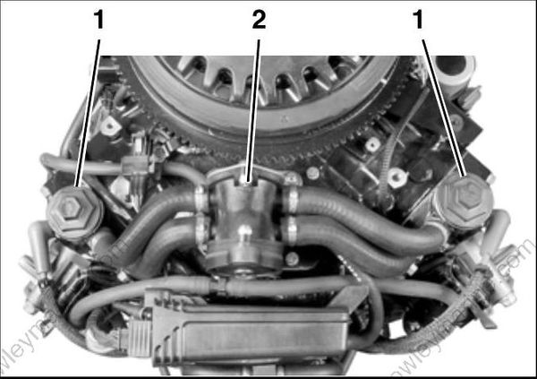
Thermostats 004269
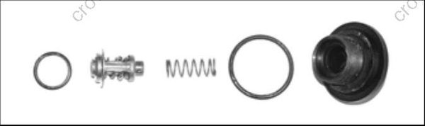
Pressure valve assembly
The thermostats and pressure valve control the flow of water entering the vertical water passages of the cylinder heads.
Water outlet passage at the bottom of each cylinder head aligns with a water outlet passage in the cylinder block. Water flows through the block to the adapter housing and then out of the outboard.
At low speed, the pressure valve is against the seat and the thermostats are closed. Warm water from the top of the cylinder block gradually migrates to the thermostat pocket at the top of each cylinder head. Water movement is the result of water “bleeding” past the pressure valve and thermostats.
The thermostat eventually opens as the water temperature in the system reaches 135°F (57°C). When thermostat opens, increased water flow is directed down the cylinder head water passage to the water outlet passage of the block. Water then exits through the adapter/exhaust housing.
At higher speeds, water pressure increases. The pressure valve opens, or lifts off the seat, at approximately 1800 RPM. Water flows through the pressure valve and bypasses the thermostats. Hoses route the water flow from the pressure valve to the vertical water passages below the thermostats. All water flows through the cylinder heads to the outlet passages of the block and then exits through the adapter housing.
This pressure controlled water outlet circuit provides a “high flow” discharge of water during high speed operation. This cooling system configuration provides “balanced cooling” at higher RPM by utilizing one pressure valve to control the discharge of water through both cylinder heads.
Refer to HOSE ROUTING AND WATER FLOW DIAGRAM on p. 216.
Refer to HOSE ROUTING AND WATER FLOW DIAGRAM on p. 216.
Additional Cooling
Two external water supply hoses direct water flow into the exhaust (plenum) area of the cylinder block. The water reduces exhaust runner temper atures and circulates through the cylinder block.
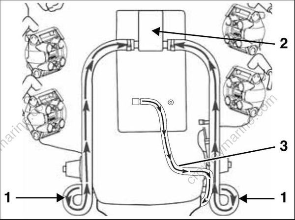
External water supply hoses 000698r
Exhaust (plenum)
Inner exhaust cooling hose
A third external water hose directs water flow from the exhaust housing of the cylinder block to an exhaust passage at the adapter. The water reduces inner exhaust temperatures and cools the propeller hub.
The base gasket limits water flow to the base of the block and diverts water flow to the rear port and rear starboard fittings of the adapter housing.
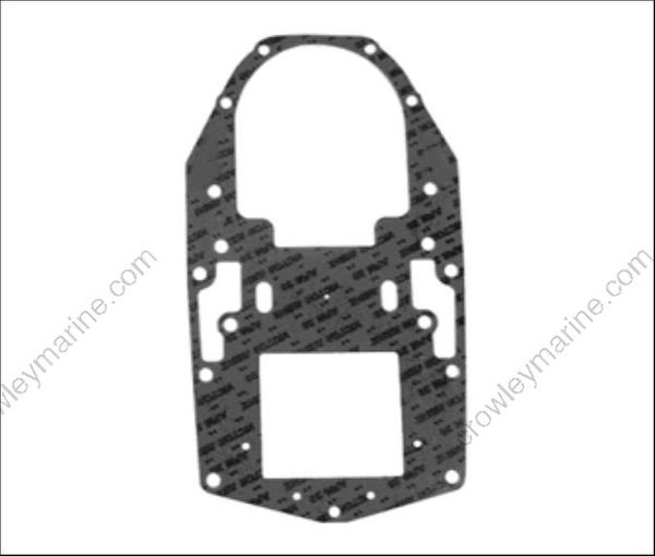
Gasket, adapter to powerhead 000661
EMM and Vapor Separator Cooling
Cooling water is routed from the top of the cylinder block to the inlet fitting of the EMM and through the EMM water cavity. Cooling of the EMM minimizes the temperatures of internal components. Cooling water from the EMM is routed to the water inlet fitting of the vapor separator water cavity. Cooling the vapor separator fuel chamber
minimizes fuel vaporization. Cooling water from the vapor separator is routed to the block and exits through the adapter/exhaust housing.
IMPORTANT: Improper EMM cooling will activate service codes (code 29 and 25) and initiate S.A.F.E. or SHUTDOWN. Refer to EMM DIAGNOSTICS on p. 104 for specific service code
information.
Disassembly
Remove the thermostat cover and O-ring from each cylinder head. Remove each thermostat.
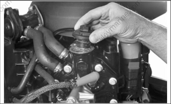
004338
Inspection
Inspect all components for cracks, heat damage, or signs of corrosion. Replace damaged components. Clean debris from all housings and thermostat components.
Assembly
Assembly is essentially the reverse of disassembly. Pay close attention when performing the fol lowing additional tasks.
Coat threads of each cylinder head thermostat cover with Gasket Sealing Compound Install and tighten the cover to a torque of 120 to 144 in. lbs. (13.6 to 16.3 N•m).
