

SERVICING – THREE PISTON SYSTEM
Disassembly
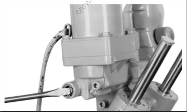
Before removing the manual release valve, operate the unit to the full UP position, then run the unit down momentarily and loosen the reservoir cap one full turn.
To avoid personal injury, always wear eye protection when servicing the hydraulic unit. Since there might be significant residual pressure behind some components, cover each component with a shop cloth as you remove it.
Thoroughly clean the unit before disassembling. Scrub all outside surfaces with a stiff brush and hot, soapy water to prevent surface dirt from contaminating internal parts.
Do not apply heat to the cylinder body or cylinders. Excessive heat can cause high
pressure leaks or failure of parts.
Always use a lint free shop cloth when handling power trim/tilt components.
If painting the unit is required, paint it after it is completely assembled. Painting of individual components may cause flakes of paint to enter the hydraulic passages during assembly. Tape the trim/tilt piston rods before painting.
Screw the manual release valve in. Remove the retaining ring using retaining ring pliers. Remove the manual release valve.
Inspect O-ring and two plastic split rings on the manual release valve for nicks and cuts. Inspect tip of valve for damage. The two plastic split rings are not available separately. If rings are damaged, replace the manual release valve.
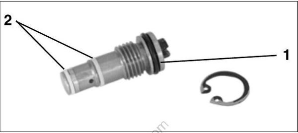
- O-ring 22863
- Plastic split rings
Remove reservoir cap and drain the fluid into a container. Inspect the O-ring in the cap.
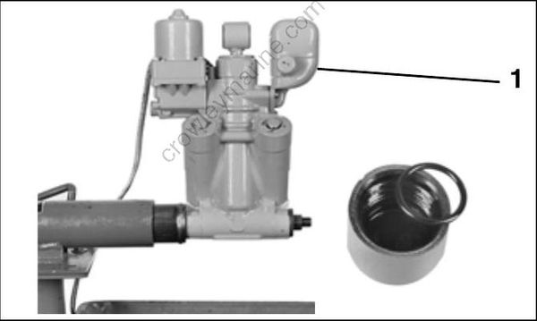
- Reservoir cap
Remove the three Pozidriv screws securing the reservoir to cylinder body. Remove reservoir.
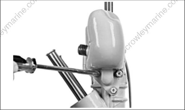
Remove the reservoir O-ring from the cylinder body. Check machined surfaces for nicks and scratches.
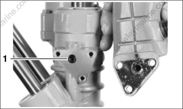
- O-ring
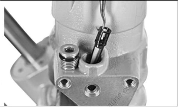
Use a 6 mm hex wrench to remove the plug from the cylinder body. Inspect the O-ring and the filter. Replace, if necessary.
Remove the four screws securing motor to pump manifold assembly.
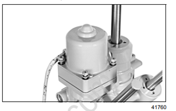
Remove the wire shield from the pump manifold. Remove the motor and inspect the motor O-ring
and the O-ring on the cable connector.
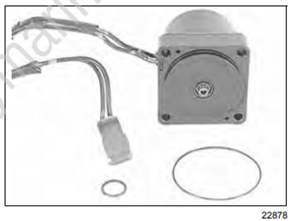
Remove and inspect the coupler. Remove the filter screen from the pump manifold. Check the machined surfaces on the manifold for nicks and scratches. The pump manifold is not serviceable. Do not remove the pump or any control valves from the manifold. Clean the screen with a mild solvent and inspect it for tears, clogging, or other damage.
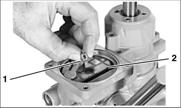
- Coupler 41763
- Filter screen
Remove the three Allen head screws securing the pump manifold assembly to cylinder body.
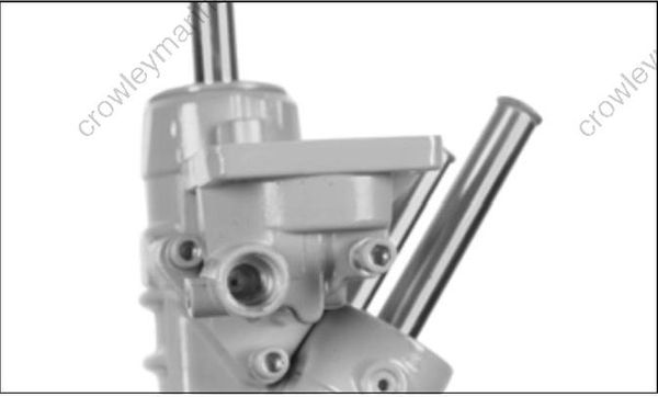
IMPORTANT: Individual parts in the pump manifold assembly are not available separately. Do not remove pump or any control valves from the body.
Remove the manifold. Remove five O-rings from cylinder body. Check machined surfaces for nicks and scratches.
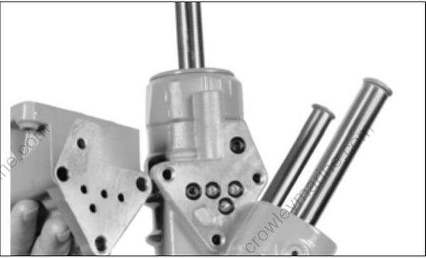
Tilt Piston Removal
Use Tilt Cylinder End Cap Remover/Installer, P/N 326485, or Universal Spanner Wrench, P/N 912084, and a breaker bar, to unscrew the tilt rod end cap.

41788
Drain the fluid from above the piston.
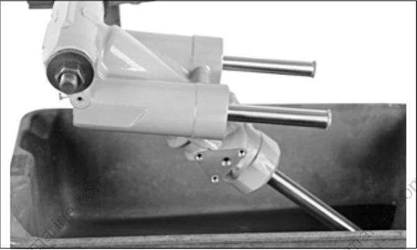
41789
Slowly pull the piston out with a rag wrapped around the rod and the top of the cylinder. Drain the remaining fluid from the cylinder.
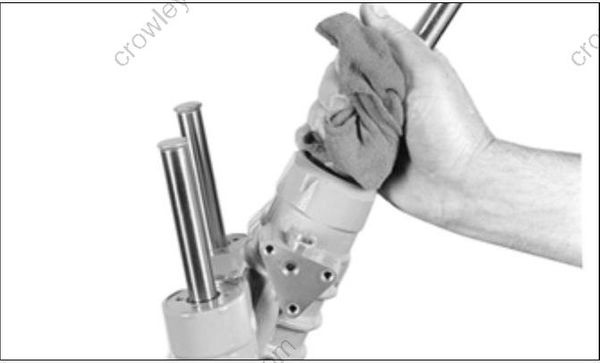
41765
Inspect the bore of the tilt cylinder for excessive scoring. If the bore of the tilt cylinder is scored or damaged, the hydraulic assembly must be replaced.
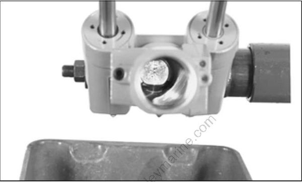
41767
Clamp the rod eye tightly in a soft jaw vise. Remove the nut from the piston end of the rod.
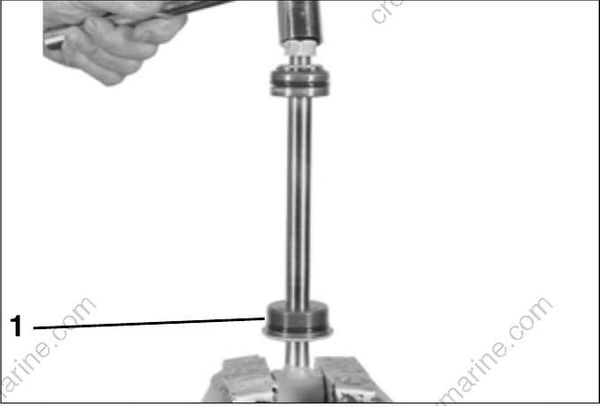
- End cap 41781
Remove the washer. Slide the tilt piston off the rod. Be careful not to lose the springs, plungers, or small check valves in the piston assembly.
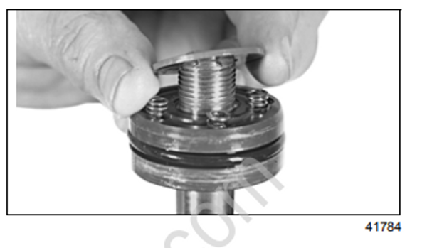
41784
Remove and discard the small inner O-ring and large outer O-ring.
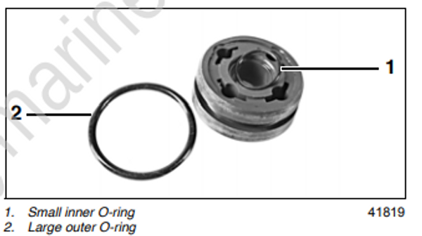
- Small inner O-ring 41819
- Large outer O-ring
Tilt Piston Identification
Different tilt pistons are used on hydraulic units for various outboard models. All plungers and check balls are identical. The tilt piston assemblies contain valving specific to certain models. To provide impact protection, it is important the correct piston assembly be installed.
Three of the four springs are one length, and the fourth spring is shorter. On assembly, the shorter spring can be positioned in any hole in the piston.
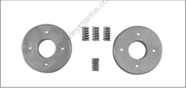
Tilt Piston Assembly
Piston check balls and plungers are identical. Lubricate and install a new outer O-ring on the tilt piston. Place one ball, one plunger, and one spring in each hole in the piston as indicated. Three of the four springs are one length, and the fourth spring is shorter. On assembly, the shorter spring can be positioned in any hole in the piston. Set piston aside.
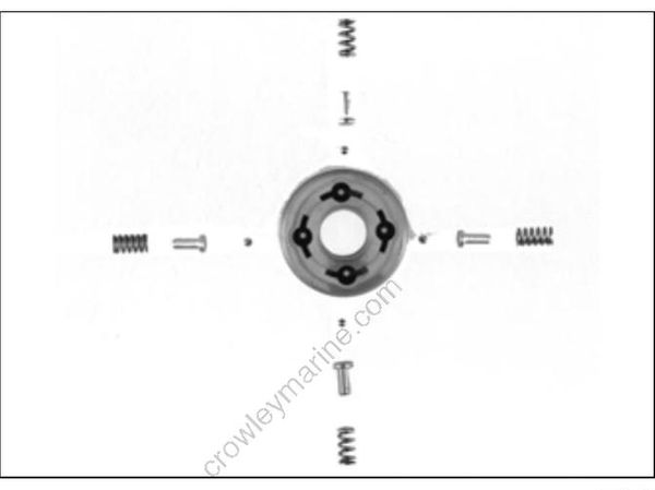
41818
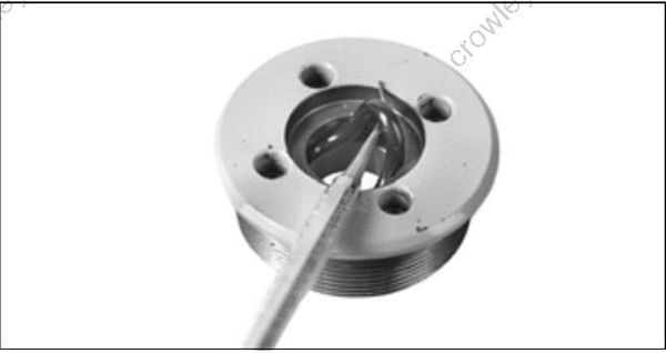
Use a screwdriver to carefully pry the scraper out of the end cap. Discard the scraper. Remove and discard the large outer O-ring.
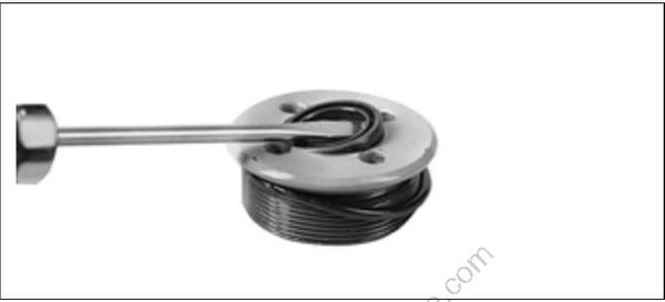
41791
Remove and discard inner O-ring of the end cap.
41792
Tilt Rod Assembly
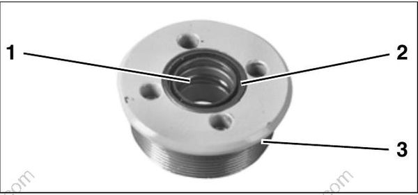
Clean the end cap thoroughly, then lubricate and install a new O-ring in the end cap. Lubricate and install a new scraper. The scraper is installed with the lip facing out. Lubricate and install a new O-ring on the outside of the end cap.
Inner O-ring 41795
Lip
Outer O-ring
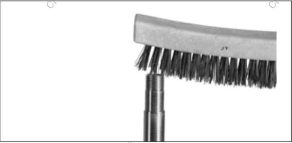
Use a wire brush to clean all thread-locking mate rial from the threads on the tilt rod.
41821
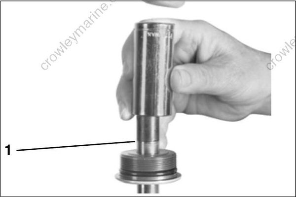
Lubricate the inside surface of the end cap. Lubricate and install Tilt Cylinder Seal Protector, P/N 326005. Use a deep-well socket and a plastic mallet to drive the end cap onto the rod, then remove the seal protector. Slide the end cap down the tilt rod.
- Tilt Cylinder Seal Protector 41824
Clean any thread-locking material from the threads on the inside of the nut. Spray threads of with Locquic Primer and let dry. Apply a small amount of Nut Lock to the threads. Slide the washer over the threads and install the nut. Torque to 58 to 87 ft. lbs. (79 to 118 N·m).
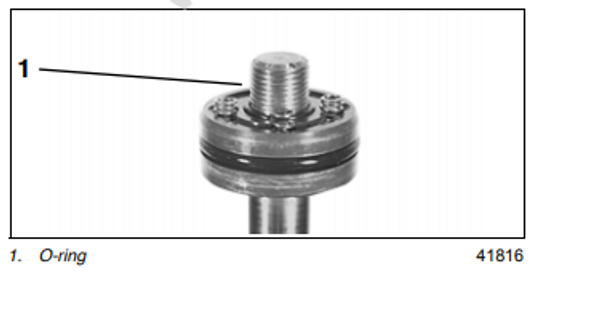
41783
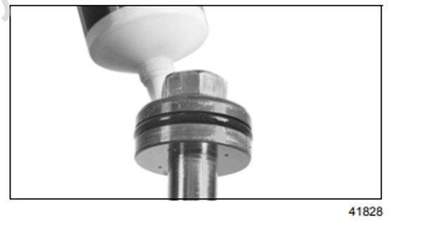
To ensure that the tilt piston has been properly assembled and the impact relief balls are properly seated, apply Power Trim/Tilt & Steering Fluid on top of the tilt piston. Fluid should not leak past the impact relief balls while seated. If fluid does leak, disassemble the piston assembly and inspect the relief ball seats. Set the tilt rod assembly aside.

41828
Trim Rod Removal
Unscrew trim cylinder end caps using Trim Cylinder End Cap Remover/Installer, P/N 436710, or
Universal Spanner Wrench, P/N 912084, and a breaker bar. Small pins must be used in the spanner wrench.
41829
Unscrew trim cylinder end caps using Trim Cylinder End Cap Remover/Installer, P/N 436710, or Universal Spanner Wrench, P/N 912084, and a breaker bar. Small pins must be used in the spanner wrench.
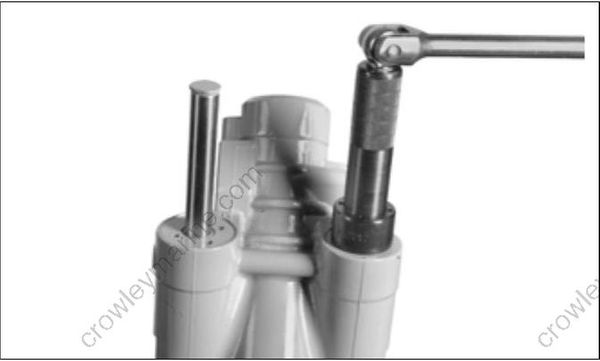
41829
Slide the caps to the end of the rods. Drain the fluid from the top of the pistons.
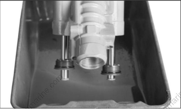
41837
Slowly pull each piston out with a rag wrapped around the rod and the top of the cylinder.
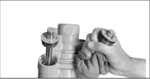
41838
Drain the remaining fluid from the cylinders. Inspect both bores of the trim cylinders for excessive scoring. If one or both trim bores are scored or damaged, the hydraulic assembly must be replaced.
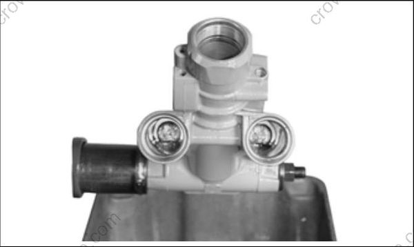
41840
Remove and discard both back-up rings and the O-ring from each trim rod piston.
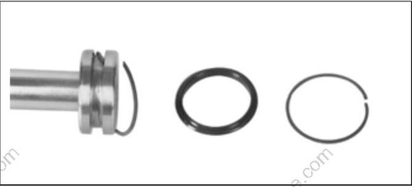
41841
Using Hydraulic Cylinder Rod Holder, P/N 983213, clamp the rod tightly in a vise. Remove the thrust pad from the trim rod, then remove the end cap.
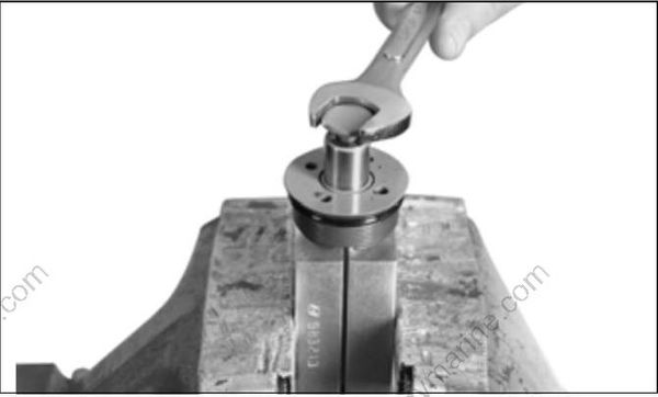
41842
Remove the rod from the vise. Use a small screwdriver to carefully pry the scraper out of the end cap. Discard the scraper.
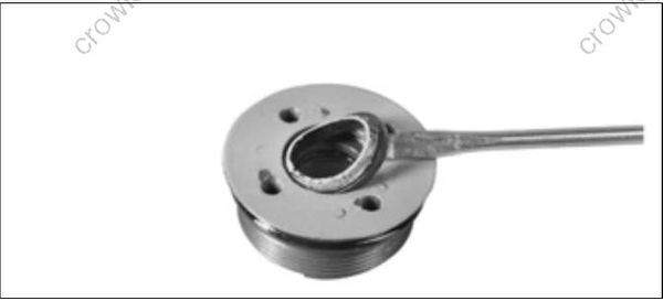
41843
Use a suitable tool to remove the inner quad-ring and the outer O-ring. Discard the quad-ring and O-ring.

41844
Trim Rod Assembly
Lubricate and install a new quad-ring and scraper in the end cap. Install the scraper with the bevel facing out. Lubricate and install a new O-ring on the outside of the end cap.
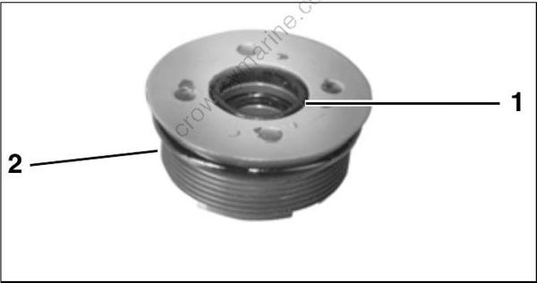
- Bevel 41845
- O-ring
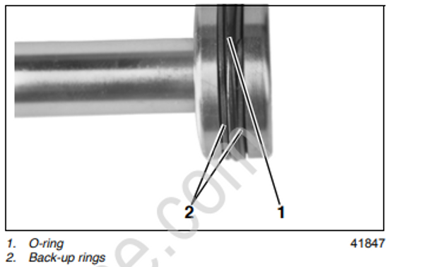
- O-ring 41847
- Back-up rings
Using Hydraulic Cylinder Rod Holder, P/N 983213, clamp the rod tightly in a vise and lubricate the cap and rod. Slide the end cap onto the rod and install thrust pad. Torque thrust pad
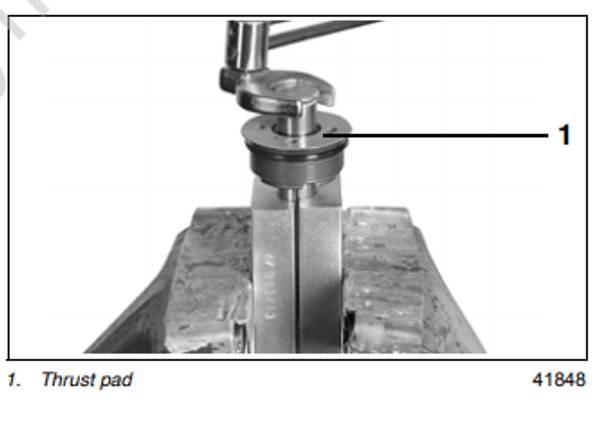
- Thrust pad 41848
Manifold and Reservoir Installation
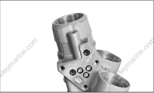
Lubricate five new manifold body O-rings. Place them in the cylinder body.
41849
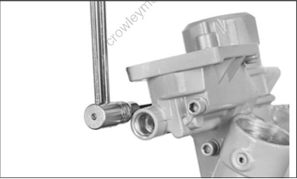
Attach the valve pump assembly to the cylinder body with three Pozidriv screws. Torque screws to 60 to 84 in. lbs. (7 to 9.5 N·m).
41850
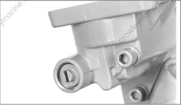
Oil and install the manual release valve. Thread the valve just past the snap ring groove. Do not install the snap ring at this time. The valve will be removed later for the Pressure Leakdown Test on p. 367.
41851
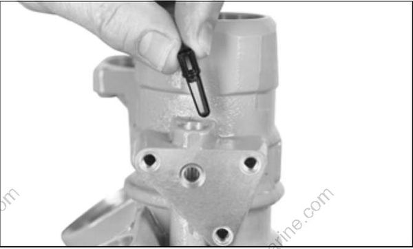
Install the reservoir filter screen in the cylinder body. Make sure the screen is seated. Install the plug, using a 6 mm Allen wrench, and tighten securely.
41863 Lubricate and place a new reservoir O-ring in the cylinder body.
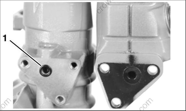
- O-ring 41865
Attach the reservoir to the cylinder body with three Pozidriv screws. Torque the screws to 35 to 52 in. lbs. (4.0 to 5.9 N·m).
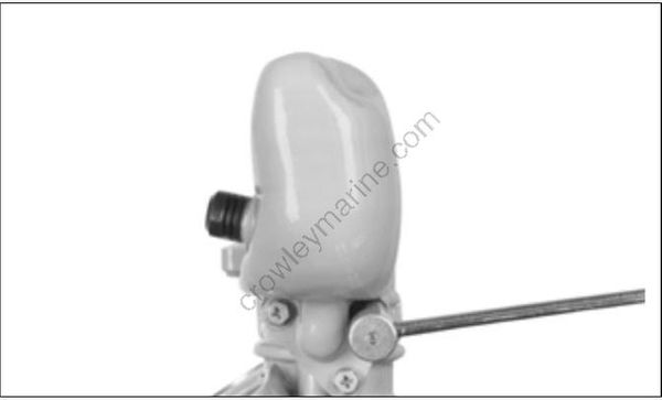
41866
Trim Rod Installation
Lubricate the trim rod pistons. Place the rod assemblies into the body. Push them in until the end caps just clear the tops of the cylinders. Fill the cylinders with Power Trim/Tilt & Steering Fluid. Failure to fill the cylinders could cause difficulty in purging air from the unit.
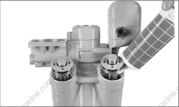
41867
Screw the trim rod end caps into the cylinder body. Use Trim Cylinder End Cap Remover/Installer, P/N 436710, or Universal Spanner Wrench, P/N 912084. Torque caps to 60
to 70 ft. lbs. (81 to 95 N·m).
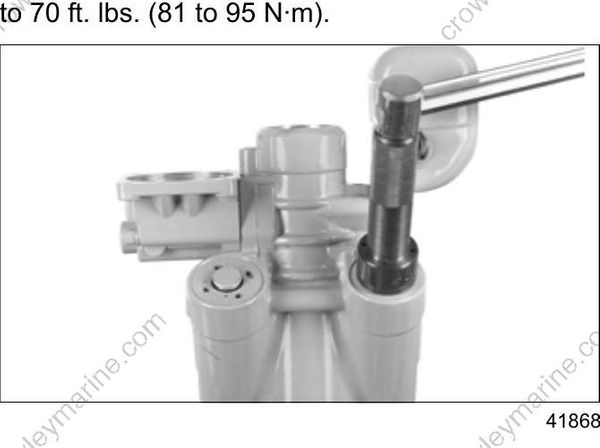
41868
Lubricate the tilt rod piston. Slide the end cap all the way up on the rod assembly. Place the piston end of the rod assembly into the cylinder body. Push it in until the end cap just clears the cylinder top. Leave enough room to pour fluid into the cylinder. Fill the cylinder with Power Trim/Tilt & Steering Fluid. Failure to fill the cylinder could
cause difficulty purging air from the unit.
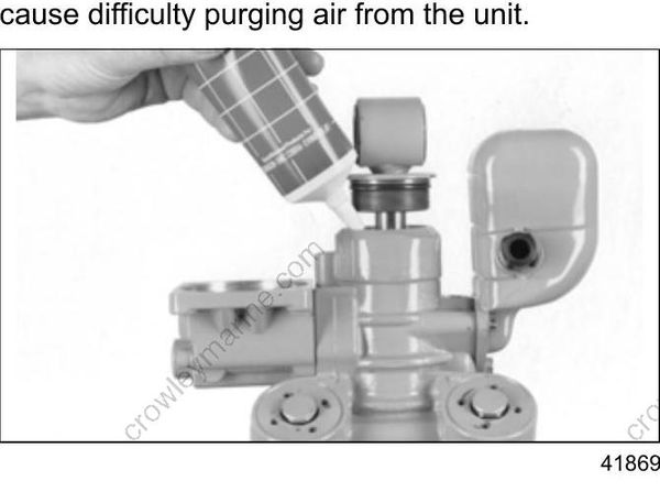
41869
Screw tilt cylinder end cap into cylinder body. Use Tilt Cylinder End Cap Remover/Installer, P/N 326485, or Universal Spanner Wrench,
P/N 912084. Torque cap to 58 to 87 ft. lbs. (79 to 118 N·m).
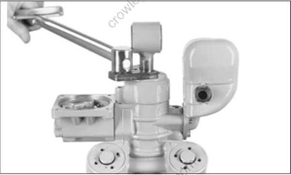
41870
Motor Installation
Position the pump manifold so the pump mounting surface is level. Install the coupler into the pump.
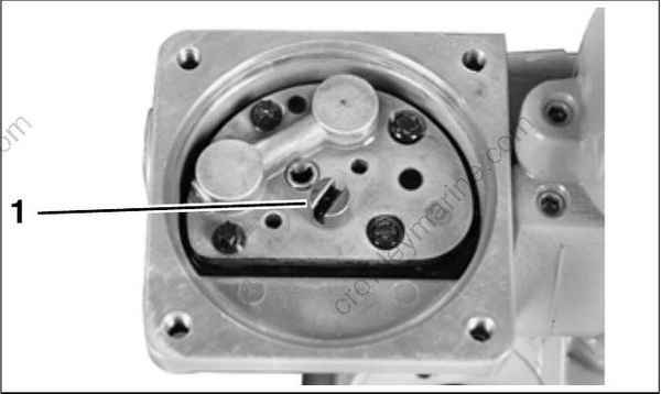
- Coupler
Fill the pump cavity with Power Trim/Tilt & Steering Fluid up to the top of the two bosses. Rotate the coupler clockwise and then counterclockwise until no more air bubbles come out of the pump.
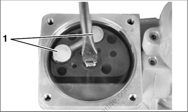
- Bosses
Install the filter screen.
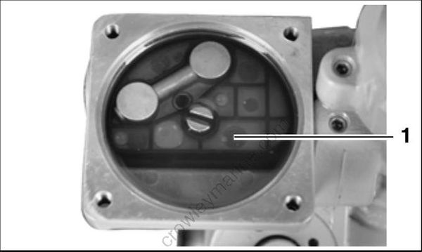
- Filter screen
Lubricate and place a new O-ring on the motor. Make sure the cable is on the transom side of the unit; align the coupler slot with the motor shaft. Place the motor on the pump manifold assembly.
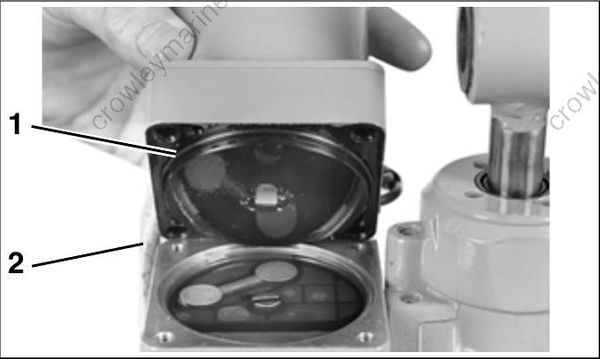
O-ring 41857
Cable
Install the four motor screws. Torque the screws to 35 to 52 in. lbs. (4.0 to 5.9 N·m).
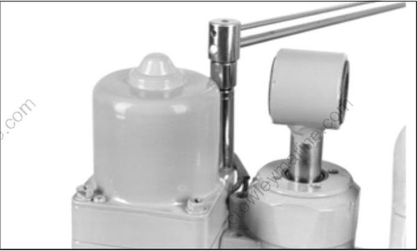
Fill the reservoir to the bottom of the fill hole with Power Trim/Tilt & Steering Fluid. Install and tighten the reservoir cap. Turn the manual release valve in until it seats. Cycle the unit up and down several times to purge air.
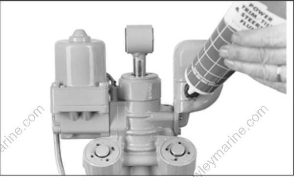
Operate the unit to the full UP position, then run down momentarily to release pressure. Check the fluid level again and add fluid, if necessary. Remember that all rods must be completely up to check the fluid level. Test the unit by performing the Pressure Leak down Test on p. 367.
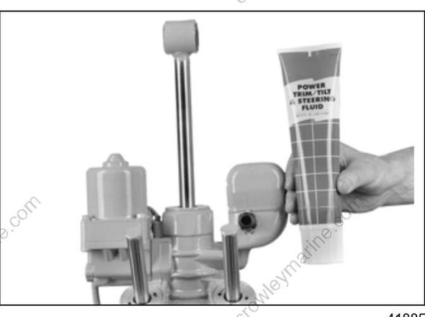
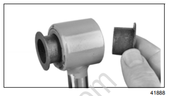
Check the tilt rod bushings. Replace them if they are worn excessively
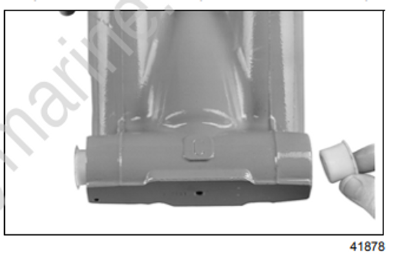
Check the bushings on the bottom of the manifold body. Replace them if they are worn excessively.
Check system operation in both trim and tilt range.
