

Protect against hazardous fuel spray. Before starting any fuel system service, carefully relieve fuel system pressure.
Refer to Relieving Fuel System Pressure on p. 189.
Use the Evinrude Diagnostics Software program to review service codes prior to troubleshooting. Correct all conditions related to service codes FIRST. Inspect all fuel hoses, filters, and connections. Check quality of fuel supply.
Manifold Pressure Test
If the outboard runs, check pressure with the out board running. Perform pressure tests outlined in FUEL COMPONENT TESTS on p. 184. If the outboard does not run, use the primer bulb to fill the vapor separator. Make sure circulation pump activates with key switch in ON position. The Fuel Pump test of the diagnostic program can be used to activate electric fuel pump.
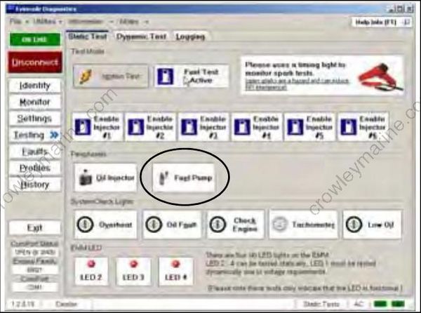
Static Tests Screen 005155
Results:
Pressure test indicates 20 to 30 psi (138 to 207 kPa):
• Circulation pump output is good. Make sure fuel system pressure does not fall below 15 psi (103 kPa) after outboard (pump) is OFF for five minutes. Leak down indicates a fuel system leak or leaking injector.
Low or no pressure, pump runs:
• Suspect damaged fuel pressure regulator in vapor separator or faulty circulation pump. Per form Pressure Regulator Test on p. 186. Pump does not run:
• Check voltage at pin 1 of fuel pump connector. Voltage should be 12 V at initial key ON, 12 V fuel pump test activated, or outboard cranking or running.
• Check voltage at pin 2 of fuel pump connector. The EMM controls power to the fuel pump (purple/black wire). Outboard must be cranking or running. Use the fuel pump test of the diagnos tic program to activate the control function of the EMM. Connect voltmeter positive lead to pin 2 and negative meter lead to ground. Activate Fuel Pump test or run outboard. Voltage reading should be 12 volts.
Excessive pressure:
• Check for restricted pressure regulator in vapor separator or restricted fuel return manifold.
Vapor Separator Checks
Fuel Supply
The vapor separator must provide “solid” fuel to the fuel circulation pump. Make sure the vapor separator receives the proper fuel supply from the fuel lift pump.
Perform Lift Pump Pressure Test on p. 187.
• Use primer to check fuel movement through fuel lift pump.
• Outboard runs: Check pressure with outboard running.
• Outboard does not run: Check pressure with outboard cranking.
Venting
Monitor the vapor separator vent hose. No fuel or a trace of fuel is acceptable. Excessive fuel dis charge indicates a vapor separator vent malfunction. Monitor vent for presence of fuel during testing. Temporarily install clear tubing for monitoring. Replace vapor separator if the venting of fuel is continuous.
Fuel Delivery to Lift Pump
Perform the Lift Pump Vacuum Test on p. 187. Make sure no restrictions or air leaks exist in the fuel supply hose or boat fuel system.
FUEL INJECTOR OPERATION
Static Tests
Perform the Fuel Injector Static Test using the diagnostic program. Static tests are performed with the outboard “static” or not running. Listen for an audible “click” from each injector when it is actuated.
IMPORTANT: This test is operating injector on 12 V battery power / system voltage (55 V). Battery must be fully charged and connections must be clean and tight. The start assist circuit (SAC) of the EMM should convert battery voltage (12 V) to 30 V of system voltage. Injector activation should be carefully confirmed.
Results:
No injectors actuate:
• Use the diagnostic software to monitor system voltage (55 V). Check individual injector circuits from EMM to injectors. See Stator Voltage Out put Test on p. 142 if system voltage is low. Some injectors actuate; some do not:
• Make sure individual injector circuits and injectors are functional. See Fuel Injectors on p. 184.
All injectors actuate:
• Confirm fuel system pressure and fuel supply to injectors.
