

COUNTER ROTATION
IMPORTANT: Counter rotation model gear cases use unique components and require different service procedures. Use care when working on counter rotation gearcases. DO NOT inter change parts between standard and counter rotation models. Pay particular attention to these procedures when working on counter rotation gearcases.
Propeller Shaft Bearing Housing Removal
Remove the two screws, washers, and retainers holding the propeller shaft bearing housing.
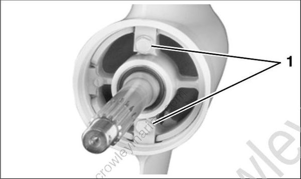
- Retainer tab screws
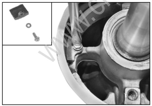
Remove wedge, screw, and washer.
To remove the propeller shaft, bearing housing and forward gear from a counter rotation gear case, thread Propeller Shaft Adapter, P/N 432398, onto Slide Hammer, P/N 432128, until it seats. Thread adapter completely onto propeller shaft and pull propeller shaft, bearing housing, and forward gear assembly out of gearcase.
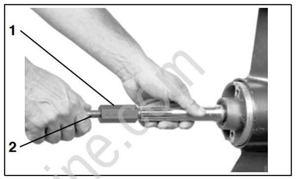
- Adapter, P/N 432398
- Hammer, P/N 432128
Shift Housing, Gear and Propeller Shaft Removal
Push down on the shift rod. This will move the detent lever downward to clear the inside of the gearcase when the shaft assembly is pulled out. Unthread the shift rod from the detent lever. Remove the six screws, shift rod, and cover from the gearcase.
Discard the cover gasket. Remove the shift rod O-ring from inside of cover and discard.
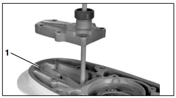
- Cover gasket
Use an appropriate tool to apply downward pressure on the detent while pulling on the propeller shaft assembly. Remove propeller shaft assembly from the gearcase.
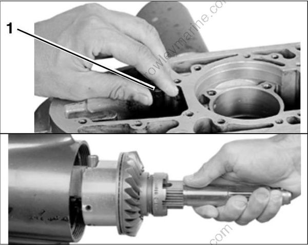
Counter Rotation Models
- Too
Shift Housing Service
Wear safety glasses to avoid injury.
Disassembly
IMPORTANT: The shift housing and forward gear bearing are serviced as an assembly. If either are worn or damaged, replace the complete assembly.
Insert a suitable tool under one end of the clutch dog spring and remove it from its groove by unwrapping it from around the clutch dog. Dis- card the spring.
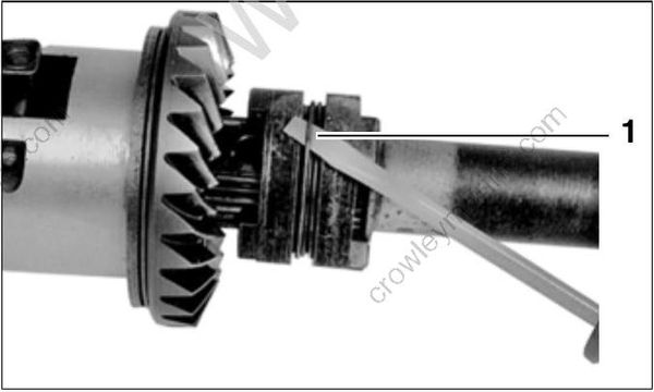
- Clutch dog spring
Push the pin out of the clutch dog. Remove all components.
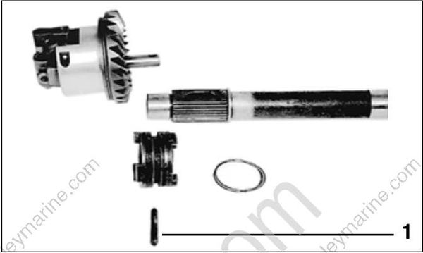
- Pin
Remove the gear, thrust bearing, and thrust washer from the shift housing.
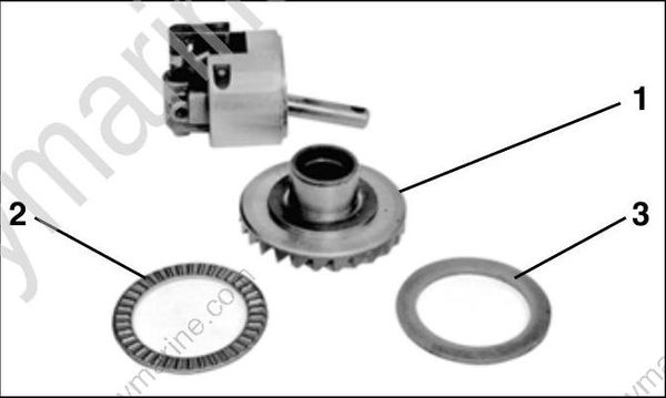
- Gear
- Thrust bearing
- Thrust washer
IMPORTANT: The shift housing supports the reverse gear on counter rotation gearcases.
Remove the shift lever pin from the housing. Remove shift shaft, cradle and shift lever. Move shifter detent accordingly to assist in removal of components.
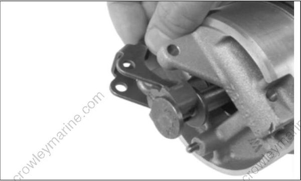
Wear safety glasses to avoid personal injury. The detent ball and spring and come out with great force.
Wrap the housing with a shop cloth to catch ball and spring. Pull the shifter detent straight out of the housing.
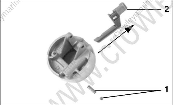
- Ball and spring
- Shifter detent
Remove the detent ball and spring.
Remove needle bearings from bearing housing for cleaning and inspection.
Assembly
IMPORTANT: Clean and inspect all components before beginning assembly procedures. Replace any damaged components.
Lightly coat the detent ball and spring with Needle Bearing grease. Insert the spring in the housing, then the ball.
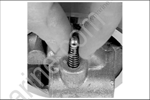
Insert shifter detent into the housing as shown, while depressing the ball and spring with a suit able tool. Once the detent is past the ball, remove the tool and position detent to engage NEUTRAL.
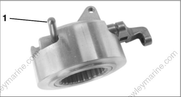
- Pin, shift lever (used as tool)
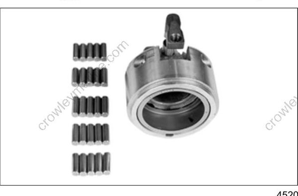
Thoroughly grease 25 needle bearings with Needle Bearing grease and place in the bearing case.
With shifter detent in NEUTRAL, install arms of shift lever into detent slots. Align the pivot holes and insert the retaining pin. Push shifter detent down.
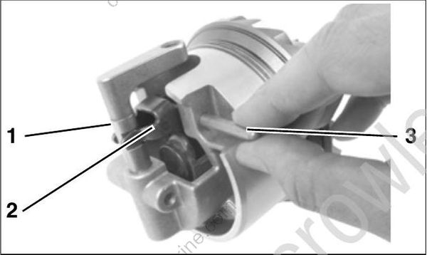
- Shifter detent
- Shift lever
- Pin, shift lever
Rest the cradle on the shift shaft.
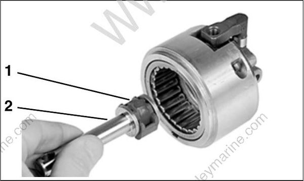
TYPICAL
- Cradle
- Shift shaft
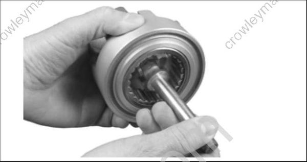
Position the shift lever arms into the recesses of the shift cradle. Pull shifter detent back up to NEUTRAL to hold the cradle and shaft in place.
Inspect clutch shaft detent balls, retainer and spring. These parts should not require removal under normal servicing.
Wear safety glasses to avoid injury.
If these parts are damaged or removed, a new service kit should be installed. Refer to correct model parts catalog for kit part number.
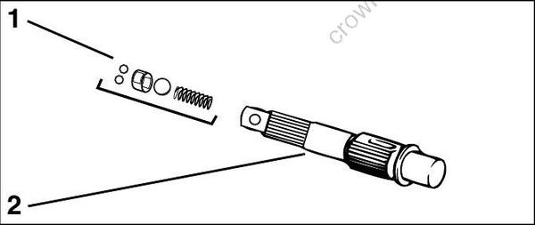
TYPICAL
- Clutch Shaft Retainer Kit
- Clutch Shaft
Coat thrust bearing and thrust washer with Needle Bearing grease. Place the bearing on the back of the gear. Set the washer on top of the thrust bearing. Insert the gear, bearing, and washer into the bearing housing.
IMPORTANT: Bearing and washer must be installed in the correct order.
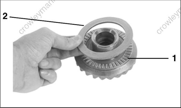
- Thrust bearing
- Thrust washer
Align holes in the clutch dog with slot in the propeller shaft. Install the clutch dog on the shaft with “PROP END” facing rear of the shaft.
IMPORTANT: The clutch dog is not symmetrical. If installed backwards, it will not fully engage and will immediately damage itself and the gears.
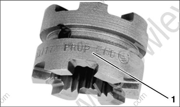
- “PROP END”
Slide the propeller shaft onto the shift shaft, align the hole in the shaft with the hole in the clutch dog, install the pin and then, a new clutch dog retaining spring. Position three coils over each end of the pin, MAKING SURE NONE OF THE COILS OVERLAP OR ARE LOOSE.
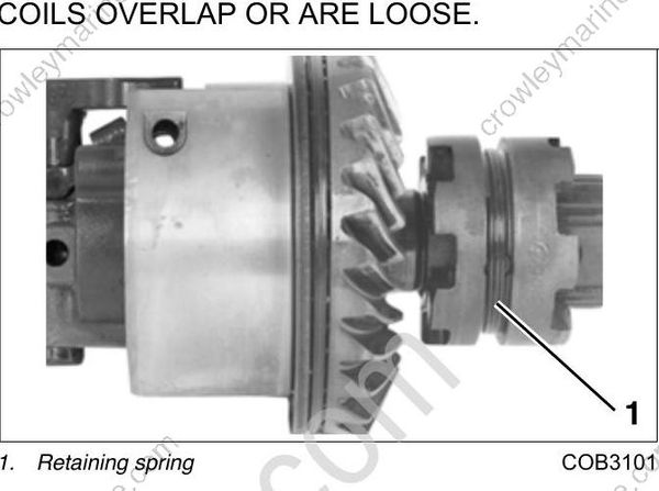
- Retaining spring
Propeller Shaft Bearing Housing and Forward Gear
Disassembly
Remove and discard the bearing housing O-ring.
Remove the anode and discard if more than two thirds deteriorated.
Clamp the bearing housing by the anode bosses in a vise, as shown. Remove the forward gear assembly by unscrewing it with Spanner Wrench, P/N 432400.
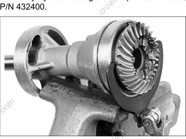
Remove gear housing retaining ring.
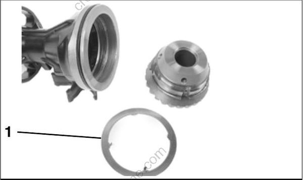
- Retaining ring
Remove the set screws and remove the flange.

Remove the shim from either the flange or forward gear.
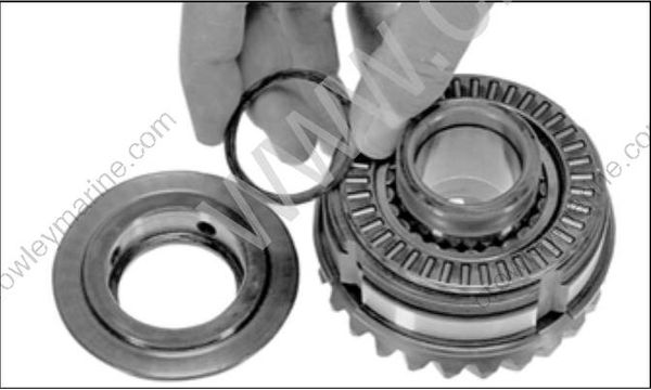
Remove the thrust bearing.
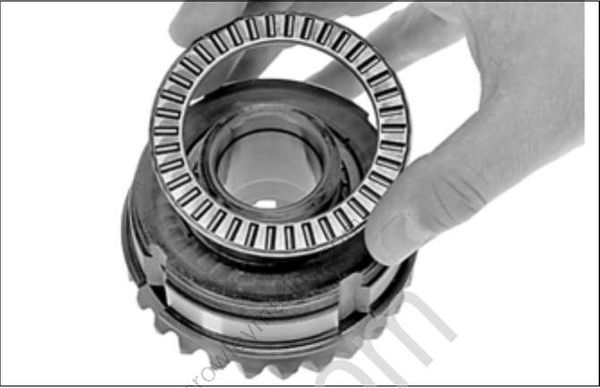
Remove the bearing housing from the forward gear.
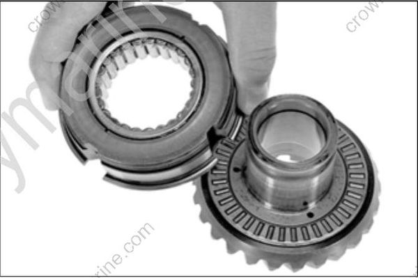
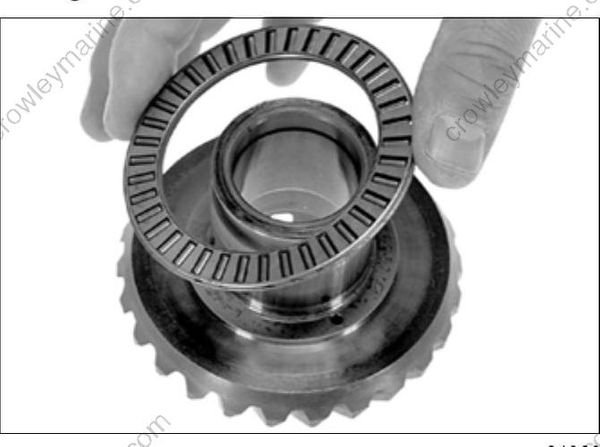
Remove the thrust bearing from the forward gear.
Inspect the forward gear for excessive wear or damage.
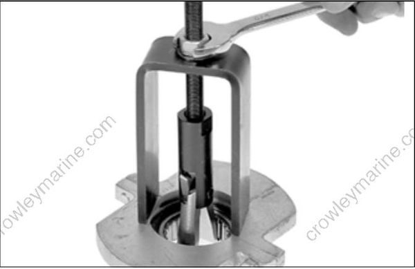
Remove the forward gear bearing only if it needs to be replaced. If removal of the bearing is necessary, use Large Puller Jaws, P/N 432129, and Puller Bridge, P/N 432127, with an appropriate base. Leave the rollers in to allow for good contact with the puller jaws.
If removed, install a new forward gear bearing. Apply Needle Bearing grease to 25 new rollers. Install the rollers in the bearing.
Using Bearing Installation Tool, P/N 339778, install the bearing, lettered side facing tool.
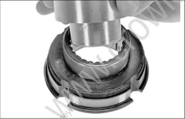
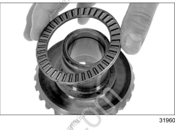
Install the thrust bearing on the forward gear.
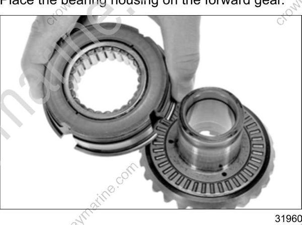
Place the bearing housing on the forward gear.
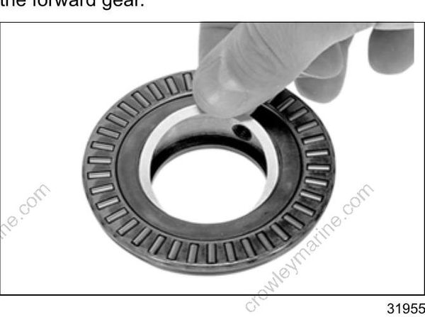
Install 0.030 in. (0.7 mm) of shims and the thrust bearing in the flange. Install the thrust bearing on the forward gear.
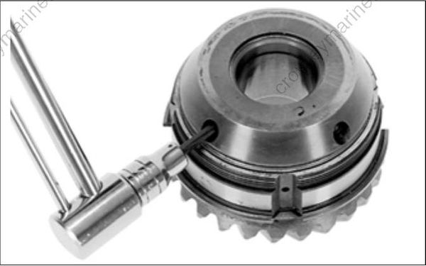
Install set screws and torque to 144 to 168 in. lbs. (16.3 to 19 N•m). Use no thread sealant.
Anchor a dial indicator gauge to a flat, level surface.
Position the gear assembly so the indicator needle makes contact with the flange on the housing. The indicator needle must be parallel with the side of the gear housing and perpendicular to the table surface. Zero the dial indicator.
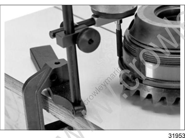
Grip the bearing housing 180° apart and pull up to get a reading on the indicator. To determine thick ness of shims; use the following example:
0.030 in. of shims in the assembly
– 0.020 in. reading on the dial indicator
= 010 in. difference
+ 0.001 in. necessary end play
= 0.011 in. required shims
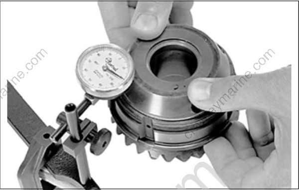
Remove the 0.030 in. (0.7 mm) of shims from the assembly. Reassemble the gear assembly using a combination of shims to achieve the required thickness. Apply Nut Lock to the threads of the set screws and torque to 144 to 168 in. lbs. (16.3 to 19 N•m).
Push propeller shaft out of the bearing housing.

Remove the thrust washer and thrust bearing.
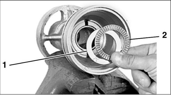
- Thrust washer
- Thrust bearing
For seal and bearing service, refer to Propeller Shaft Bearing Housing Seals and Bearings on p. 350.
Assembly
Apply Needle Bearing grease to the thrust bearing. Position bearing around shoulder on the propeller shaft.
Apply Needle Bearing grease to the thrust washer. Place washer in recess of bearing housing.
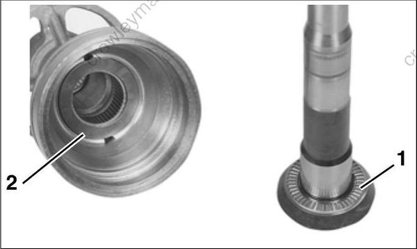
- Thrust bearing
- Thrust washer
Coat bearing surfaces of propeller shaft with gear case lubricant. Slide the propeller housing onto the propeller shaft.
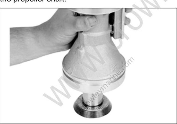
IMPORTANT: Use caution when assembling the propeller shaft in the bearing housing. Thrust bearing must remain around shoulder on the propeller shaft.
Install gear housing retaining ring as shown.
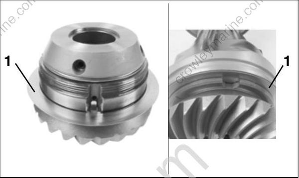
- Retaining ring
Apply gearcase lubricant to the threads of the forward gear.
IMPORTANT: To prevent damage to threads, install forward gear by hand until fully seated against propeller shaft bearing housing.
Use Spanner Wrench, P/N 432400, to tighten the gear assembly to a torque of 100 ft. lbs. (136 N·m).

Inspect the anode. Replace if necessary. Torque screws to 108 to 132 in. lbs. (12.2 to 14.9 N•m).
Propeller Shaft Bearing Housing Seals and Bearings
Rear Seal Removal
Remove seals using Puller Bridge, P/N 432127, and Small Puller Jaws, P/N 432131. Position the plate on top of the housing to support the bridge, and tighten jaws securely behind the inner seal.
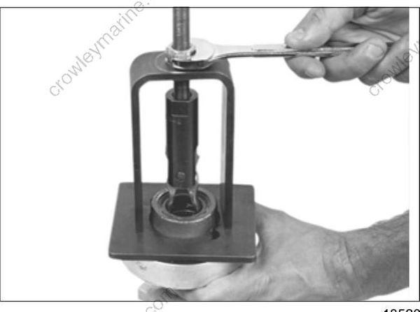
Bearing Removal
Rear seals must be removed if bearing replacement is needed. See Rear Seal Removal on p. 326.
IMPORTANT: Inspect bearings in place. If a bearing is removed for any reason, it must be dis carded.
Remove either bearing using Puller Bridge, P/N 432127, and Large Puller Jaws, P/N 432129. Rest the puller plate on top of the housing to support the bridge, and tighten the jaws securely behind the bearing.
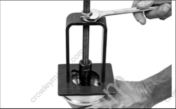
Inspect the bearing housing anode. Replace anode if it is reduced to two-thirds of original size.
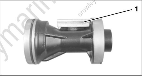
- Anode
Discard the bearing housing O-ring. Clean the housing and bearings in solvent and dry thoroughly. If bearings were not replaced, rotate the needles to check for freedom of movement.
Inspect O-ring groove, and sand off any sharp edges that would cut O-ring and prevent its sealing. Check for and remove any nicks or burrs on front of bearing housing.

- O-ring groove
Bearing Installation
Oil, then install new bearings in bearing housing.
Place the lettered end of the bearing case on the bearing installer, then press the bearing into the housing until the tool seats. When installed, the lettered end of the bearing should be visible.
Bearing Installation Tool:
- P/N 339750 – rear (counter rotation only)
- P/N 432401 – forward (counter rotation only)
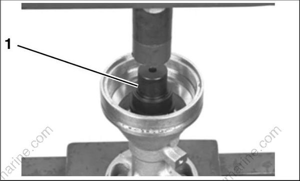
Forward Bearing – Counter Rotation
- Forward bearing installation tool
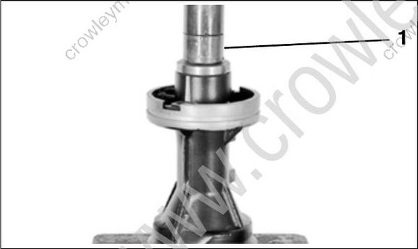
Rear Bearing
- Bearing installation tool
Rear Seal Installation
Install new seals back to back in bearing housing using Seal Installer. Apply Gasket Sealing Com- pound to metal casings of the seals before installing.
Install inner seal with lip facing toward the bearing housing, then outer seal with lip facing away from the bearing housing.
Seal Installation Tool:
• P/N 326551 – “S” Type gearcases
• P/N 336311 – “O,” “L,” and “M” Type gearcases

- Inner seal
- Outer seal
Apply Triple-Guard grease to seal lips.
Install bearing housing anode. Torque screws to 108 to 132 in. lbs. (12.2 to 14.9 N•m).
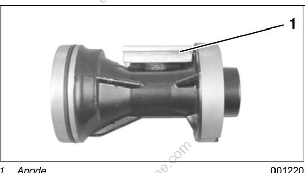
- Anode
Propeller Shaft Bearing Housing and Gear Installation
Oil and install thrust bearing and thrust washer on the hub of reverse gear. Slide the gear assembly onto the propeller shaft until it engages the pinion gear.
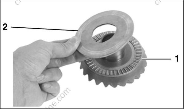
- Thrust bearing
- Thrust washer
Lightly apply Gasket Sealing Compound to a new bearing housing O-ring. Install O-ring in groove in the housing.
Install housing into gearcase, aligning screw holes with retainer slots in gearcase.
IMPORTANT: The propeller shaft must engage the clutch shaft and the forward gear must fully engage the pinion gear.
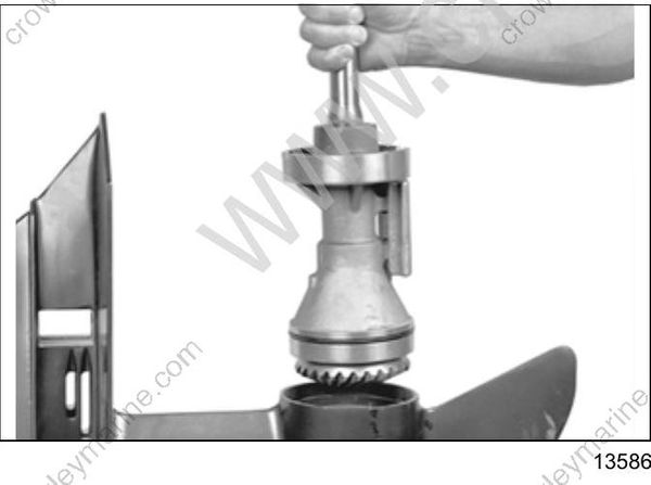
Housing must be completely seated to install retainer tabs.
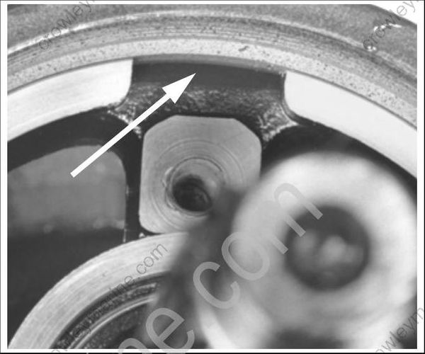
Retainer Tab Notch
Install two retainers, washers and screws. Apply Ultra Lock to threads and torque screws to 18 to 20 ft. lbs. (24 to 27 N•m).
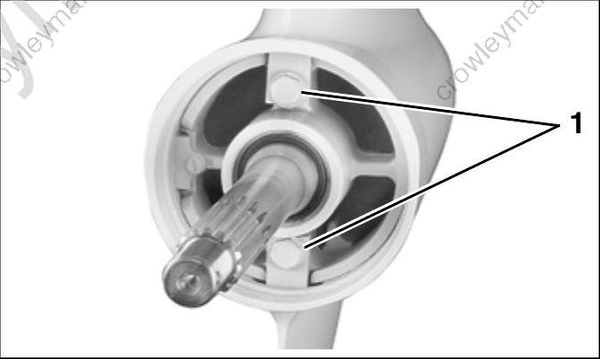
- Retainer tab screws
Loosen retainer screws 1/4 turn.
Install wedge, screw, and washer. Apply Ultra Lock to threads and torque screw 15 to 20 in. lbs. (1.7 to 2.3 N•m).

Re-torque two retainer screws to 18 to 20 ft. lbs. (24 to 27 N•m).
Confirm that torque on the wedge screw is 15 to 20 in. lbs. (1.7 to 2.3 N•m).
To complete gearcase assembly, refer to:
- LEAK TEST on p. 308
- WATER PUMP on p. 311
- SHIFT ROD ADJUSTMENT on p. 314
- REMOVAL AND INSTALLATION on p. 308
- LUBRICANT on p. 307
- Propeller Hardware Installation on p. 74
- Trim Tab Adjustment on p. 77
During break-in period of a reassembled gear case, change the gearcase lubricant between 10 to 20 hours of operation.
