

OIL COMPONENT SERVICING
To prevent accidental starting while servicing, disconnect the battery cables at the battery.
IMPORTANT: Access to certain oil distribution hoses requires removal of various engine components. Refer to service information in the various sections of this manual for additional information related to the removal and installation of specific components. DO NOT disassemble or replace any oiling system components until you are familiar with the entire OILING SYSTEM section.
Oil Distribution Hoses
The oil distribution hoses to each cylinder MUST be the same length. DO NOT alter the length of any hoses.
Manifold to cylinder block fitting hoses and manifold to oil to fuel check valve hose:
- 23 in. (584 mm)
Removal
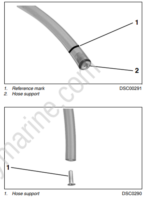
The oil distribution manifold has oil hose retainer mechanisms incorporated into the design. Use a pen or marker to mark the position of the oil hose relative to the retaining mechanism. Release the hose by depressing the outer ring of the hose retaining mechanism.
Once hose is removed from the manifold, make sure hose support is in end of the hose.
Installation
Installation is essentially the reverse of removal. Pay close attention when performing the following additional tasks.
Insert hose support in manifold end of hose.
IMPORTANT: DO NOT reinsert the hose into manifold without the hose support.
Be sure the hose is fully inserted into manifold. The insertion depth of hose into the manifold is 5/8 in. (16 mm). Visually inspect for hose supports. Hose supports are seen through hoses.
Oil Tank Assembly
Removal
Disconnect the battery cables at the battery.
Remove engine covers and air silencer.
Disconnect the electrical connector to the oil injection pump and manifold assembly.
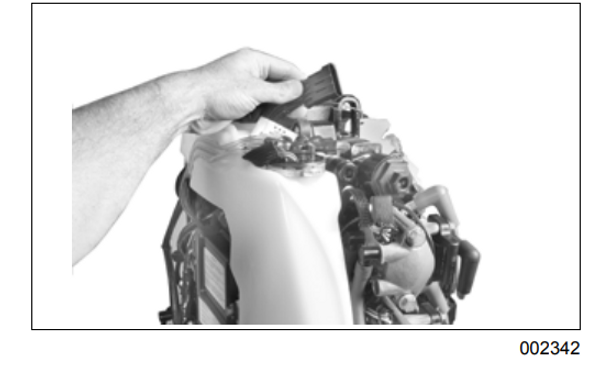
IMPORTANT: Note oil distribution hose routings before proceeding with disassembly. Clamps and protective sleeves are used to position and protect the oil distribution hoses.
Remove oil distribution hoses from the crankcase fittings and the oil-to-fuel check valve.
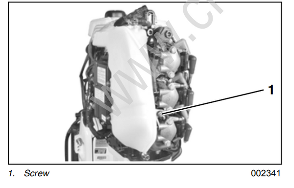
Remove oil tank retaining screws and nut.

Installation
Position oil tank assembly on powerhead. Clean mounting screws and apply Nut Lock to threads of screws. Install screws and torque to 30 to 42 in.
lbs. (3.4 to 4.8 N·m). Install nut and torque to 30 to 42 in. lbs. (3.4 to 4.8 N·m).
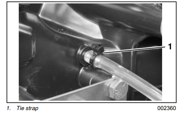
Route oil distribution hoses from the oil distribution manifold to the crankcase oil delivery fittings. Install protective sleeves and route hoses as they were prior to removal. See Oil Supply and Distribution Diagram on p. 182. Connect oil hoses to crankcase fittings and fasten with tie straps.
Run outboard and check for leaks. Use the Evinrude Diagnostics Software program to activate “Oil Prime.” Check oil flow through oil distribution hoses. Check oil system operation and routing of oil system hoses.
Repair any oil leaks and kinked or misrouted hoses. Reinstall engine covers and air silencer.
