

STERN BRACKET, 40 – 60 HP Power Tilt
the hole in the outer housing and the alignment pin into the adapter housing.
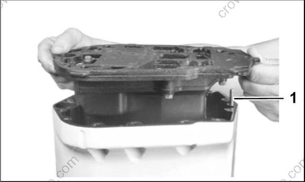
- Alignment pin
Apply Gasket Sealing Compound to threads of the four retaining screws and tighten to a torque of 60 to 84 in. lbs. (7 to 9.5 N·m).
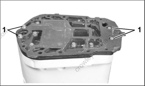
- Adapter retaining screws
Stern Bracket Disassembly
Remove the bumpers from the upper mount retaining screws. Remove the screws, upper mount, and ground lead from the bracket.
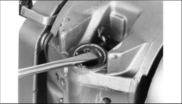
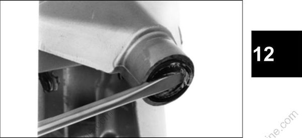
Pull the steering arm out of the swivel bracket. Use an appropriate tool to pry the upper and lower seals from the swivel bracket.
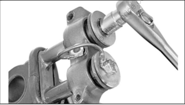
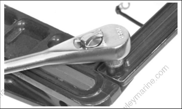
To separate the swivel bracket from the stern bracket, remove one tilt tube nut.
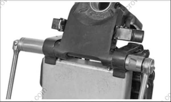
Remove the tie bar to separate the two stern brackets.
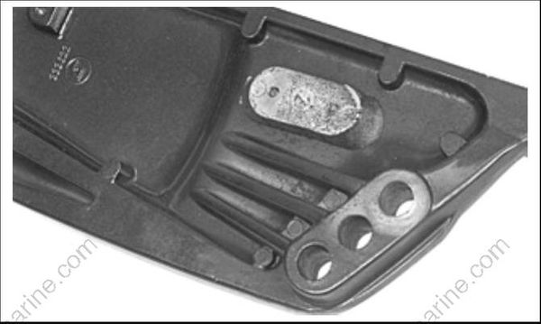
Check the condition of the anode. Replace the anode if it has been reduced to two-thirds its original size.
Stern Bracket Assembly
Assemble the tie bar to the stern brackets. Place the ground lead and starwasher between the port stern bracket and tie bar.
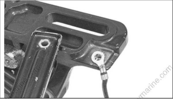
Lubricate the swivel bracket bushings with Triple-Guard grease. Place the bushings in the swivel bracket.
Position the swivel bracket between the stern brackets. Place a thrust washer between each of the stern brackets and the swivel bracket.
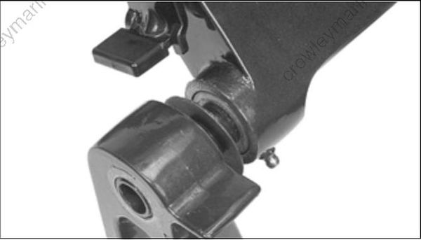
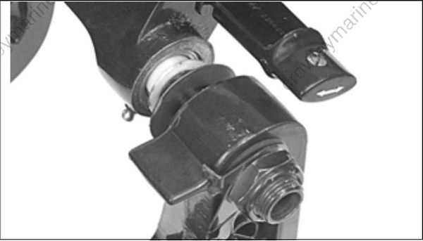
Install the tilt tube. Tighten the tilt tube nuts 40 to 45 ft. lbs. (54 to 61 N·m), then back off 1/8 to 1/4 turn.
Apply Nut Lock to threads of the upper mount to steering arm screws. Install the mount and tighten the screws 24 to 26 ft. lbs. (32.5 to 35 N·m). Make sure to place the ground lead under the starboard screw.
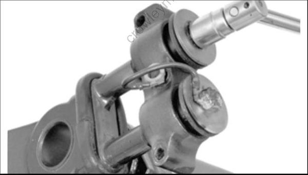
Apply a liberal amount of Adhesive 847 to heads of the upper mount screws.
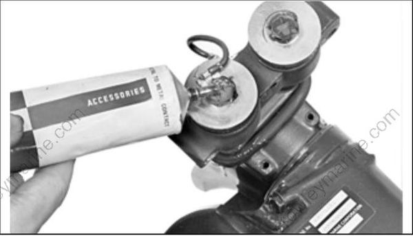
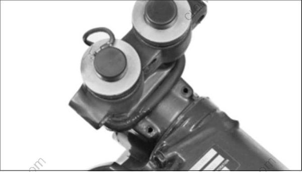
Place the bumpers on the upper mount screws.
STERN BRACKET, 75 – 90 HP Power Tilt
Stern Bracket Removal
Before servicing the stern bracket:
Remove gearcase. Refer to GEARCASE REMOVAL AND INSTALLATION on p. 354.
Remove powerhead. Refer to POWERHEAD REMOVAL on p. 228.
Remove exhaust housing. Refer to Exhaust Housing Removal on p. 284.
Remove power trim/tilt unit. Refer to TRIM AND TILT SERVICE on p. 388.
Stern Bracket Disassembly
Remove and discard steering shaft locknut.
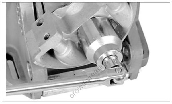
Remove the lower mount bracket and keeper.
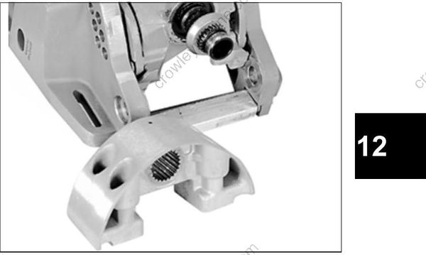
Lower mount bracket – 20” Models
