

STERN BRACKET, 40 – 60 HP Manual Tilt
Install the steering shaft keeper. Apply Locquic Primer and Nut Lock to the splines of the steering shaft and lower mount bracket.
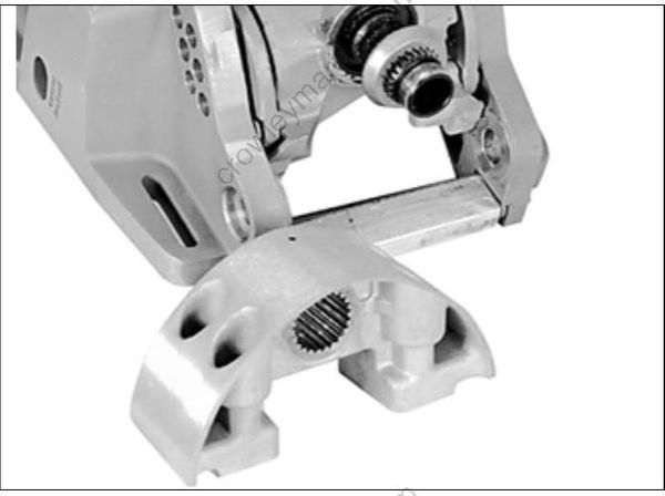
Install the lower mount bracket and a new locking nut with its unstaked side facing the mount bracket. Align the bracket with the steering arm and tighten the nut to a torque of 130 to 150 ft. lbs. (176 to 204 N·m).

Fill the swivel bracket with Triple-Guard grease through the grease fitting on the bracket’s port side. Lubricate the tilt tube, swivel bracket, and stern brackets through the two forward grease fit tings.
Install the exhaust housing. Refer to Exhaust Housing Installation on p. 285.
Clamp Screw
Stern Bracket Disassembly
Remove bumpers from the upper mount retaining screws.
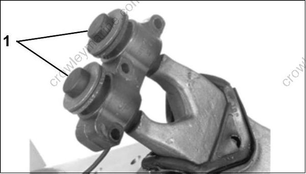
- Bumpers
Remove screws, upper mount, and ground lead from the bracket.
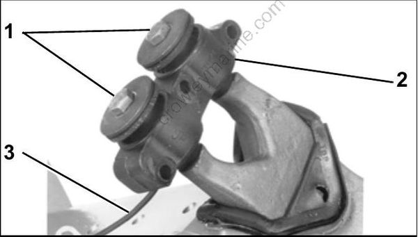
Screws
Upper mount
Ground lead
Slide the pivot shaft and upper thrust washer out of the swivel bracket.
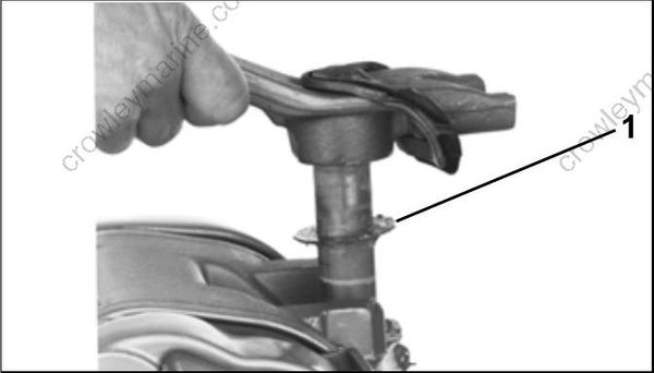
- Upper thrust washer
Use an appropriate tool to pry the upper and lower seals from the swivel bracket.
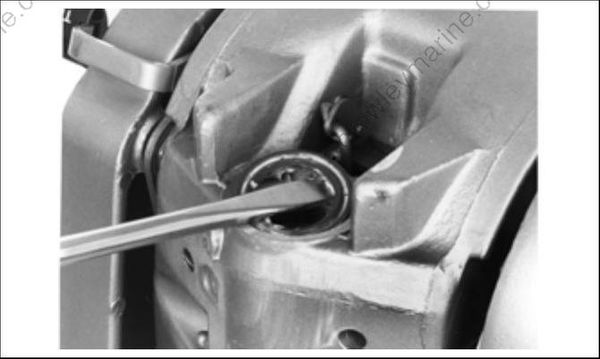
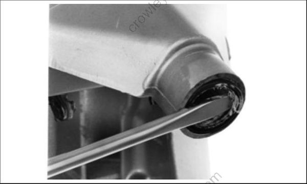
Loosen the steering friction screw while pushing outward on the steering friction pin. When the pin is flush with the inside surface of the casting, remove the steering friction thrust ring.
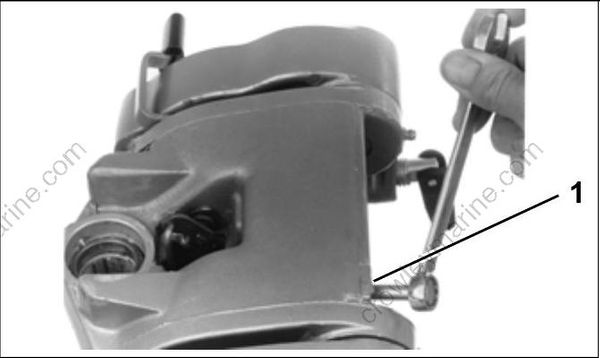
- Steering friction screw
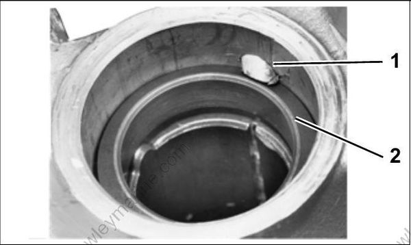
Steering friction pin
Steering friction thrust ring
Tighten the steering friction screw until the steering friction pin can be removed. Then, remove the steering friction screw.
Remove the two setscrews from the swivel bracket.
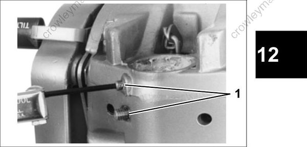
- Setscrews
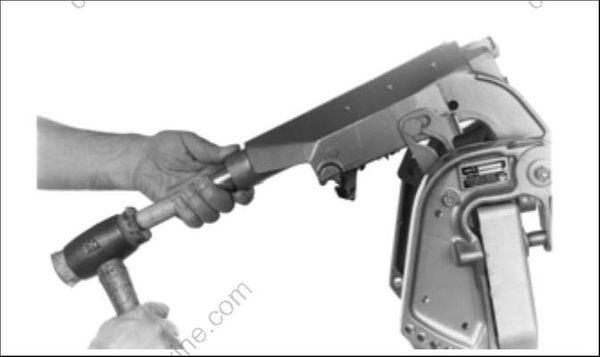
Drive the steering friction bushing up and out of the swivel bracket.
Remove the thrust rod from the stern brackets. Remove one tilt tube nut, and remove tilt tube from the stern brackets and swivel bracket. Remove the port and starboard stop link screws and nuts from the stern brackets.
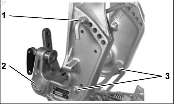
Thrust rod
Tilt tube nut
Stop link screw and nut
Remove the two stern bracket flange screws and separate the stern brackets from the swivel bracket.
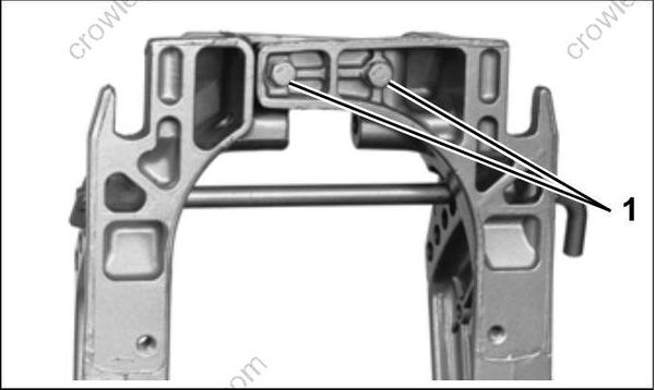
- Flange screws
Place the tilt/run lever in the RUN position. Loosen the bellcrank setscrew.
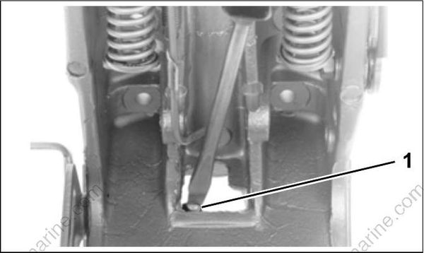
- Bellcrank setscrew
Remove the tilt/run lever, port stop link, and bushing from the swivel bracket.
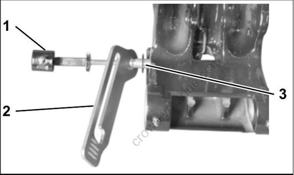
Tilt/run lever
Port stop link
Bushing
Remove the starboard stop link retaining screw and nut from the swivel bracket.
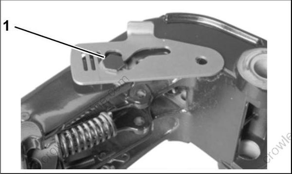
- Starboard stop link screw
Remove the cotter pins from both reverse lock pins. Remove the reverse lock pins and springs.
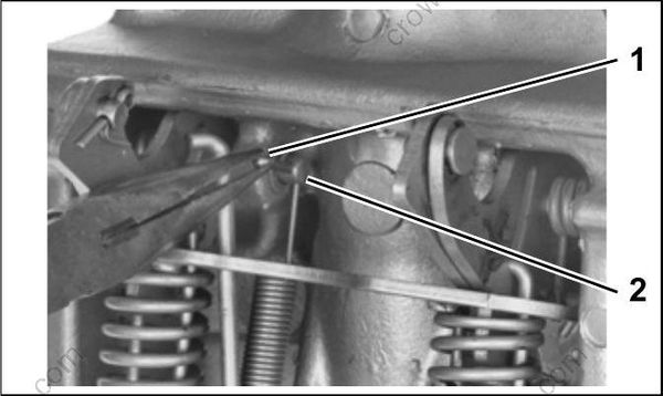
Cotter pin
Reverse lock pin
Remove the reverse lock assembly from the swivel bracket.
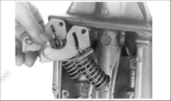
Stern Bracket Assembly
Place the reverse lock springs in the swivel bracket. Insert the reverse lock pins in the swivel bracket and part way through the reverse lock springs. Place the reverse lock assembly between the springs. Push the pins through the springs and the reverse lock assembly.
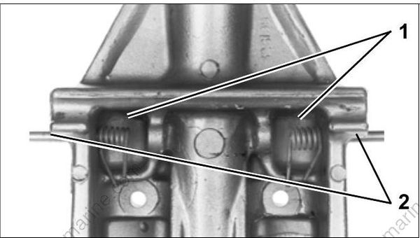
Reverse lock springs
Reverse lock pins
Install the washers on the reverse lock pins. Install the link spring on the port pin. Install the two cotter pins in the reverse lock pins.
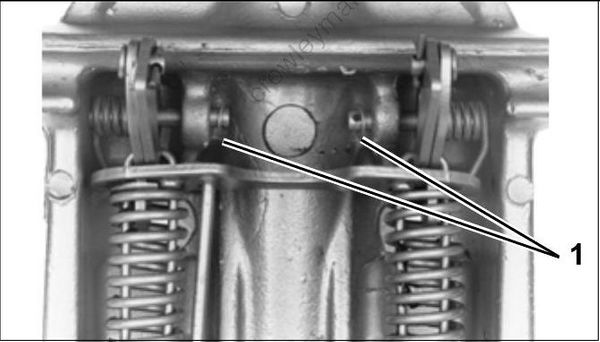
- Washers
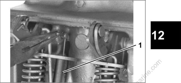
- Link spring
Install the bushing, the port stop link, and the tilt/run lever in the swivel bracket. The tilt/run lever should be in the RUN position.
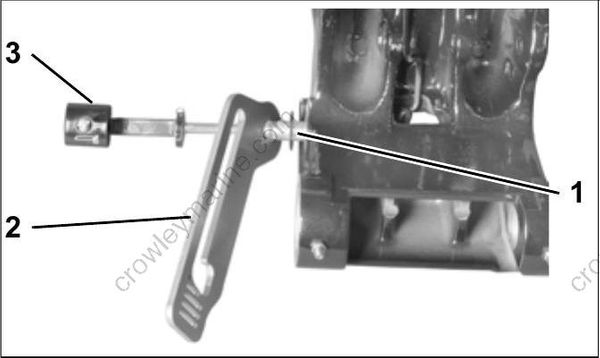
Tilt/run lever
Port stop link
Bushing
Install the wave washer and the bellcrank on the tilt/run shaft. Tighten the setscrew.
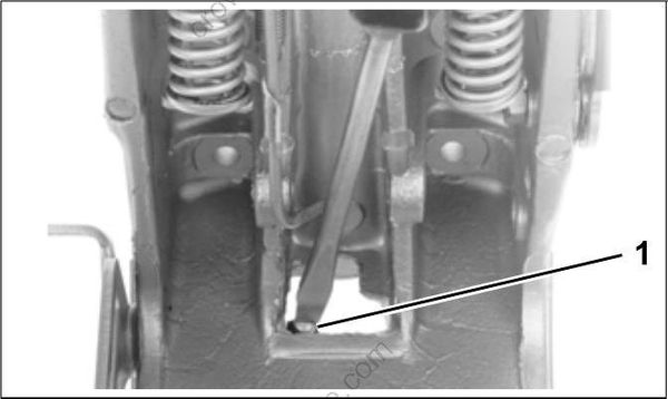
- Bellcrank setscrew
Install the starboard stop link on the swivel bracket. Install and tighten the screw and the nut to a torque of 144 to 168 in. lbs. (16 to 19 N·m).
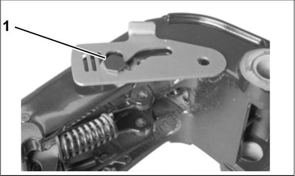
- Starboard stop link screw
Place the swivel bracket between the stern brackets.
Install the tilt tube through the following parts and install the tilt tube nuts loosely:
Starboard stern bracket
Thrust washer
Bushing
Swivel bracket
Bushing
Thrust washer
Port stern bracket
Apply Nut Lock to threads of the two flange screws. Install the two screws through the star board stern bracket flange into the port stern bracket flange. Tighten the screws to a torque of 144 to 168 in. lbs. (16 to 19 N·m).
Tighten the tilt tube nuts to a torque of 45 to 50 ft. lbs. (61 to 68 N·m).
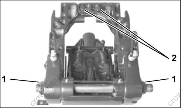
Tilt tube nuts
Flange screws
Install the thrust rod in the stern brackets.
Install the larger shoulder screw through the port stop link, wave washer, and port stern bracket.
Install and tighten the nut to a torque of 144 to 168 in. lbs. (16 to 19 N·m).
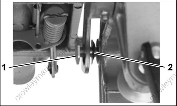
Port stop link screw
Wave washer
Install the smaller shoulder screw through the starboard stop link and stern bracket. Install and tighten the nut to a torque of 144 to 168 in. lbs. (16 to 19 N·m).
Apply Ultra Lock to threads of large setscrews. Install the screws in the swivel bracket so that one thread remains outside the casting.
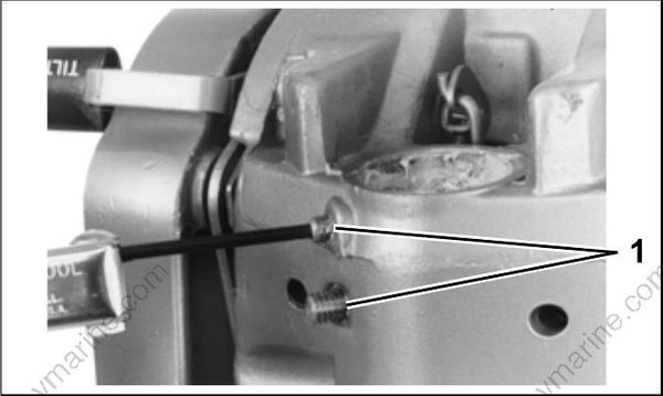
- Setscrews
Place the steering friction bushing in the swivel bracket with groove in line with the setscrews.
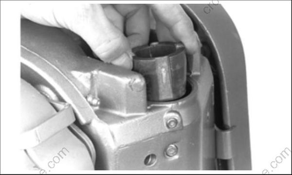
Apply Triple-Guard grease to the steering friction pin. Install the pin in the swivel bracket flush with inside surface. The pin should point up.
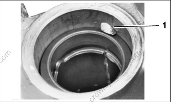
- Steering friction pin
Install the steering friction thrust ring, bevel side up, in the swivel bracket. Thread the steering friction screw in the swivel bracket. Turn the screw until the steering friction pin makes contact with top of the thrust ring. Do not tighten the screw.
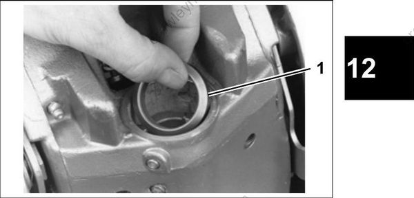
- Steering friction thrust ring
Install new upper and lower seals in the swivel bracket with lips of seals facing away from the bracket.
Slide the upper thrust washer on the pivot shaft. Slide the pivot shaft through the swivel bracket.
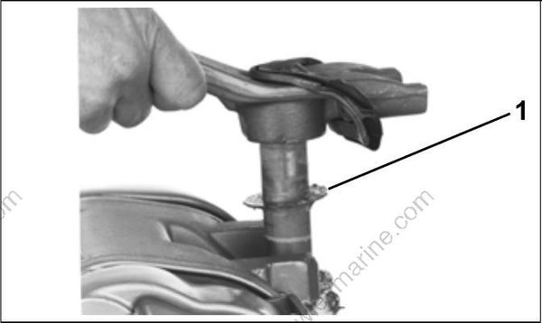
- Upper thrust washer
Lubricate the swivel bracket through the four lubrication fittings with Triple-Guard grease.
Apply Nut Lock to threads of the upper mount to steering arm screws. Position the upper rubber mount, the upper mount washers, and the retaining washers on the steering arm with the word “UP” on the mount facing up. Be sure to place the ground lead between the mount (starboard side) and the steering arm. Install and tighten the mount retaining screws to a torque of 24 to 26 ft. lbs. (32.5 to 35 N·m).
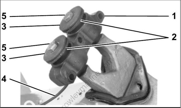
Upper mount
Upper mount washers
Retaining washers
Ground lead
Retaining screws
Place the mount screw bumpers on the upper mount screws.
Tilt Assist Cylinder
The tilt assist cylinder can be replaced without dis assembly of the stern brackets.
Support the outboard with a suitable hoist.
Remove port stop link screw. Push port stop link down to clear upper pivot pin access hole.
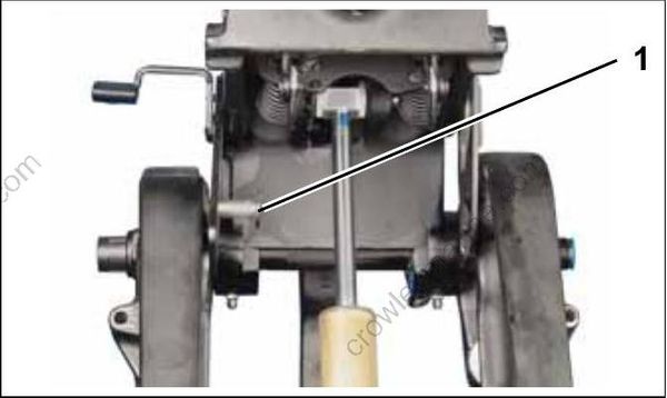
- Stop link screw
006651 Remove both cotter pins and washers. Use appropriate tool to remove upper pivot pin.
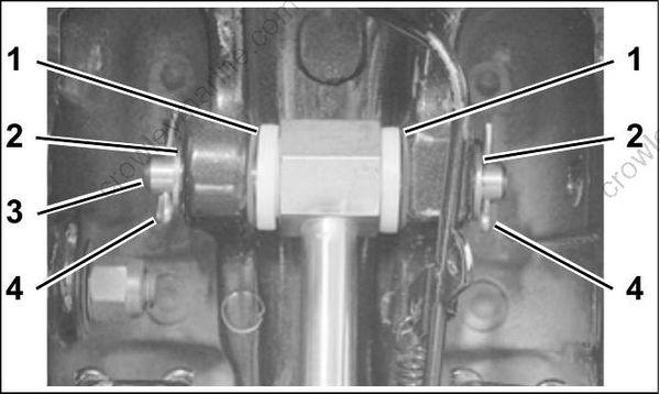
Bushings
Washers
Pivot pin
Cotter pins
The starboard stern bracket includes an access hole for the lower tilt pin.
Remove set screw from starboard stern bracket lower pivot pin access hole and use an appropriate tool to remove lower pivot pin.
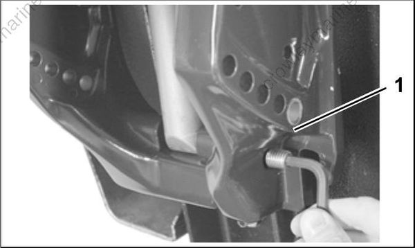
- Lower pivot pin access hole
If lower pivot cannot be removed because of corrosion or damage, stern brackets may need to be disassembled.
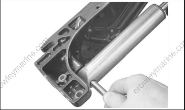
Assembly is the reverse of disassembly. Install new cotter pins in upper pivot pin. Install a new set screw in starboard stern bracket lower pivot pin access hole and tighten securely.
Disassembly
Loosen set screw and remove reverse lock release collar.
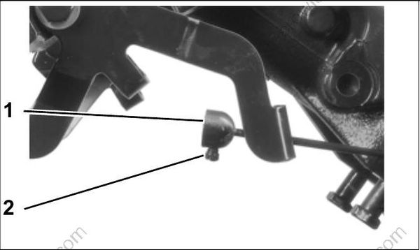
Reverse lock release collar
Set screw
Remove reverse lock springs from locking lever and reverse lock spring screws.
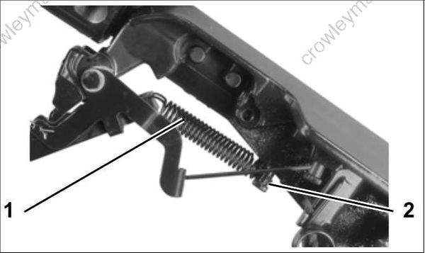
Reverse lock springs
Reverse lock spring screws
