

EXHAUST HOUSING, 40 – 65 HP
The exhaust housing contains no serviceable internal parts. The exhaust water valve and the exhaust relief muffler can both be serviced without removing the exhaust housing.
Exhaust Housing Removal
Before removing the exhaust housing:
• Remove the gearcase. Refer to Gearcase GEARCASE REMOVAL AND INSTALLATION on p. 296.
• Remove the powerhead. Refer to Powerhead POWERHEAD REMOVAL on p. 190.
Remove the three lower mount cover screws.
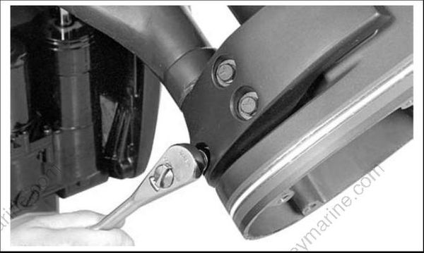
17527
Separate lower mount covers from swivel bracket.
Check condition of the lower front mount and two lower side mounts.
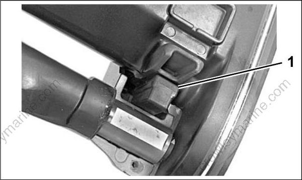
17526
- Lower front mount
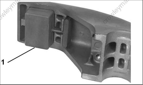
17524
- Lower side mount
Remove the three upper mount to exhaust housing screws. Be sure to support exhaust housing so it does not fall.
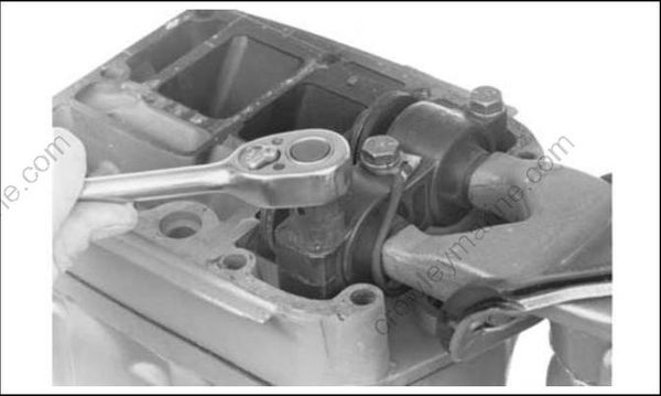
COA2943
Remove the exhaust housing.
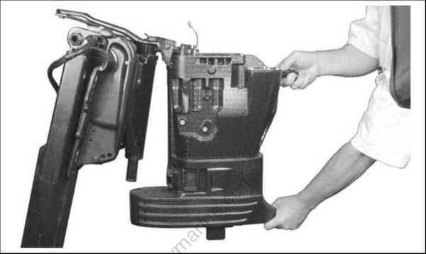
005069
Exhaust Housing
Exhaust Water Valve (60–65 HP)
Disconnect water valve electrical connector.
Remove screws and bracket holding valve to exhaust housing.
Remove tie straps and disconnect water valve hoses (3) from exhaust housing.
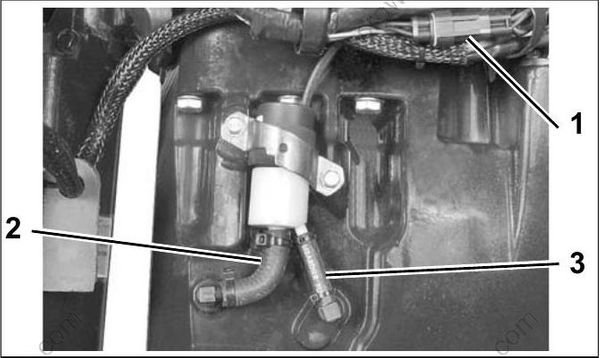
004293
- Electrical connector
- Inlet hose
- Outlet hose
Check that all water passages are clear.
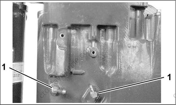
004300
- Fitting, water passage
Install hoses to fittings on exhaust housing.
Place water valve and bracket in position.
Apply Nut Lock to screws, install and tighten 60 to 84 in. lbs. (7 to 9.5 N.m).
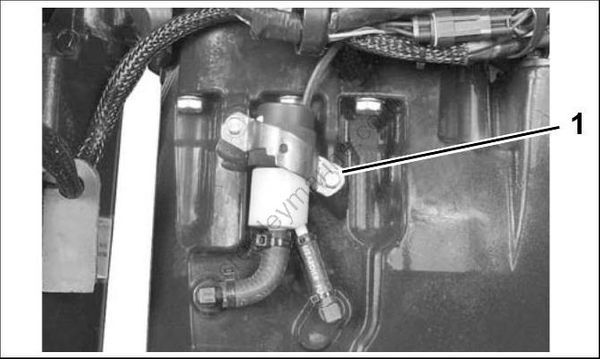
004293
- Exhaust water valve screws
Exhaust Relief Muffler
Remove exhaust relief muffler cover to inspect filter element. Clean or replace as needed.
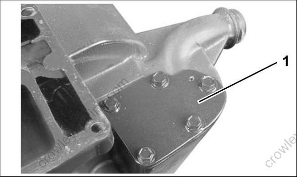
004301
- Exhaust relief muffler cover
Exhaust Housing Installation
Bring the exhaust housing into position with the stern bracket.
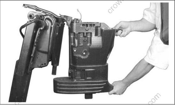
005069
Exhaust Housing
Apply Nut Lock to threads of the upper mount screws. Install the screws and place ground lead under the center screw. Tighten screws to a torque of 18 to 20 ft. lbs. (24 to 27 N·m).
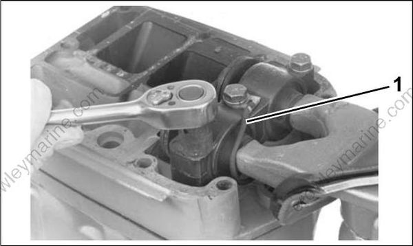
005069
- Ground lead COA2943
Place lower thrust washer on the steering shaft and place the lower front mount into position.
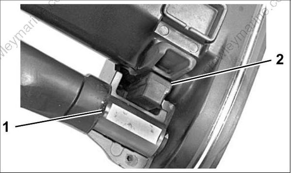
17526
- Thrust washer
- Lower front mount
Install lower side mount covers. Install and tighten the screws in stages to a torque of 16 to 18 ft. lbs. (22 to 24 N·m) following sequence shown.
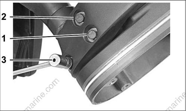
17528
Torque sequence
Install gearcase. Refer to Gearcase GEARCASE REMOVAL AND INSTALLATION on p. 296.
Install powerhead. Refer to Powerhead POWERHEAD INSTALLATION on p. 216.
