

EXHAUST WATER VALVE TEST
Disconnect electrical connector from water valve solenoid. Use an ohmmeter to measure solenoid resistance.
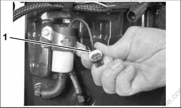
- Water valve electrical connector
| Water Valve Solenoid Resistance |
|---|
| 295 Ω ± 20 @ 77°F (25°C) |
SystemCheck CIRCUIT TESTS
Make sure the SystemCheck engine monitor can warn the operator during a “NO OIL,” “WATER TEMP” or “HOT,” “CHECK ENGINE,” or “LOW OIL” condition. Check the condition of the warning system and associated wiring and connections. Test the engine monitor regularly and anytime you suspect an alert situation has been missed.
The instrument harness must be connected to the outboard before performing the following tests. Refer to the Engine Wiring diagram and the MWS Instrument Wiring diagram in the back of this manual.
IMPORTANT: Use jumper wires made with the appropriate terminals to test the warning circuits.
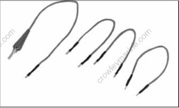
Gauge Self-Test Check
Turn the key switch to ON with the outboard NOT running. The gauge warning lights for NO OIL, WATER TEMP, CHECK ENGINE, and LOW OIL must all light at once, then turn off in sequence, and the warning horn must sound for one-half second.
If the gauge lights do not turn on, turn the key switch OFF. Disconnect the gauge 8-pin connector from the back of the gauge and turn the key switch ON. Test for battery voltage between
