

COMPONENTS
The oiling system consists of the following components:
- Oil tank
- Oil injection pump and manifold assembly
- Oil pressure sensor
- Electrical circuit
- LOW OIL and NO OIL warning systems
- Cylinder and crankcase
- Rear oil manifold assembly
- Oil recirculation system
Oil Tank Assembly
The oil tank must be properly positioned and the oil supply must be monitored. Refer to Oiling System Set-Up on p. 35.
Oil Tank Components:
- Tank, 1.8 or 3.0 gallon capacity
- Oil pickup and filter assembly
- LOW OIL sending unit
- Mounting bracket and hardware
- Protective cover (1.8 gallon tank only)
- Primer bulb and supply hose.
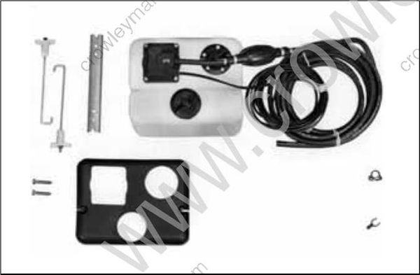
1.8 Gallon Oil Tank Kit
Oil Injection Pump
The oil injection pump is an electric (55 V) actuator style pump. It draws oil from the oil tank through the oil supply hose [25 ft. (7.6 m) maxi mum] and supplies pressurized oil to the oil manifold. The EMM supplies 55 V and controls activation of the pump.
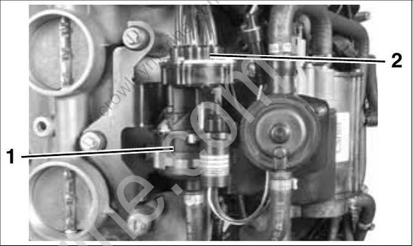
- Oil injection pump
- Oil manifold
The oil manifold distributes the oil supplied by the oil injection pump. A pressure sensor monitors the oil injection pressure.
Oil Pressure Sensor
The oil pressure sensor reacts to changes in oil manifold pressure. The EMM supplies and monitors electrical current to the sensor.
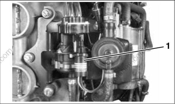
- Oil pressure sensor
The sensor provides an output voltage to the EMM based on oil manifold pressures.
- 5 VDC Input on RED wire
- 0.5 4.5 V Output on TAN / WHITE wire
- Ground on BLACK wire
The EMM monitors the oil pressure sensor’s electrical circuit. If circuit voltage is beyond the specified range (< 0.15 V, > 4.85 V), the EMM:
| Stores service code 71 |
|---|
| EMM LED 3: ON (Running) |
If oil pressure is below expected range (< 0.4 V), the EMM:
| Stores service code 72 |
|---|
| EMM LED 3: ON (Running) |
If oil pressure is above expected range (> 4.6 V), the EMM:
| Stores service code 73 |
|---|
| EMM LED 3: ON (Running) |
Refer to Oil Pressure Sensor on p. 96.
Electrical Circuit (55 V)
The oil injector is powered by the 55 V electrical circuit. The EMM controls pump operation by rap idly connecting and disconnecting the pump’s internal coil to ground.
The EMM monitors the oil injection pump electrical circuit. If circuit voltage is beyond the specified range (open circuit), the EMM:
| Activates S.A.F.E |
|---|
| Stores service code 34 |
| EMM LED 4: ON (Running) |
| Engine Monitor NO OIL display: ON |
LOW OIL Warning
A sending unit in the oil tank pick-up assembly monitors the oil level in the oil tank. This sending unit turns on the Engine Monitor LOW OIL display when the oil level falls below one-quarter capacity. An optional oil tank sending unit kit is available to display actual oil level through an I-Command net work.
NO OIL Warning
The EMM monitors the electrical circuit of the oil pressure sensor. If the sensor or circuit fails, or if there is a lack of oil pressure in the oil distribution manifold, the EMM:
| Activates S.A.F.E |
|---|
| Stores service code 38 |
| EMM LED 4: ON (Running) |
| Engine Monitor NO OIL display: ON |
Cylinder and Crankcase
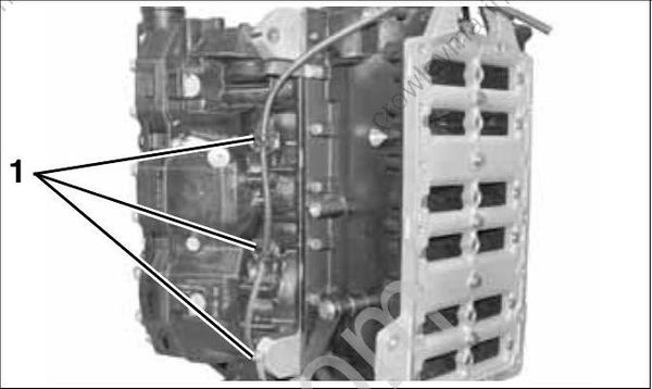
The primary oil distribution manifold provides crankcase lubrication through oil distribution hoses and pressed-in fittings at the front of the crankcase, port side.
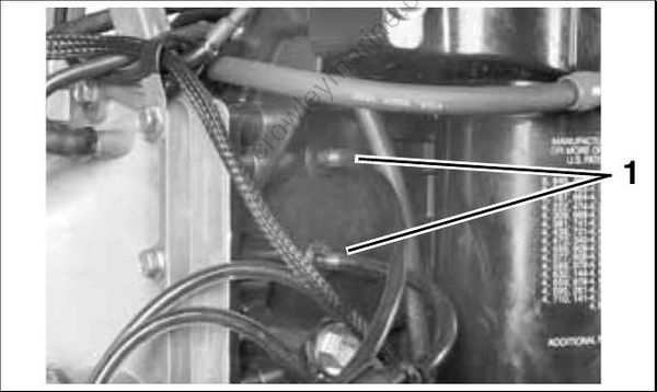
- Pressed-in fitting
The rear oil distribution manifold provides lubrication for each cylinder. Each cylinder of the cylinder/crankcase has a pressed-in fitting which is connected to an oil distribution hose.
Additionally, one oil distribution hose is routed to a tee fitting at the top of the block, above #2 cylinder.
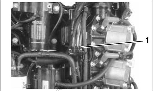
- Rear oil manifold
Oil Recirculation System
External hoses and fittings, internal cylinder/crankcase passages, and intake manifold passages are used to re-circulate any accumulation of oil from various locations in the powerhead. The movement of oil is controlled by check valves.
Cylinder Recirculation
Internal powerhead oil drain passages connect the lowest point of the intake port area of the cylinder block to external thread-in check valves. External hoses connect these check valves to a hose fitting pressed into the top of the intake manifold / throttle body. Intake manifold vacuum draws any accumulation of oil from the intake port area of the cylinders into the incoming air stream in front of the top reed valve.
- Check valves
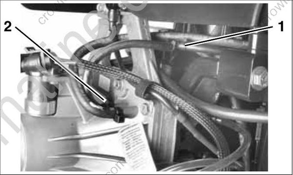
- Recirculation hose
- Hose fitting
Check valves pressed into the crankcase below #4 and #6 reed valve assemblies connect to hoses which route to a tee fitting at the top of the block, above #2 cylinder.
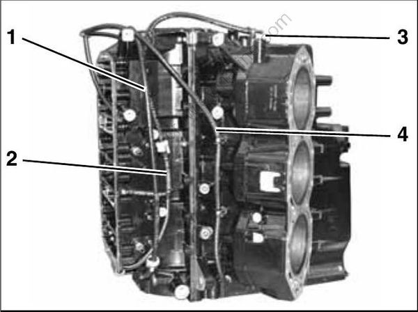
- Lower to upper main bearing oiling circuit
- Idle oil circuit
- Tee fitting
- Cylinder recirculation circuit
Crankcase / Main Bearing Recirculation
The movement of oil through the main bearings is controlled by internal passages, external fittings and hoses, and an in-line check valve.
Both center main bearings receive oil through grooved passages in the crankcase. Oil migrates to the bearings from the crankcase areas of the higher cylinders.
The lower main bearing receives oil through a grooved passage in the crankcase.
Lower to upper main bearing oil flow
Lower main bearing cavity through internal crank case passage to external fitting, external hoses with in-line check valve to external fitting at upper main bearing, and into upper main bearing through internal crankcase passage.
OIL CONTROL SETTINGS
Oil Priming
The oiling system of the outboard must be primed:
- When the outboard is first installed.
- Whenever the oil supply to the oil lift pump is disconnected or disrupted.
- Whenever an oiling system component is removed or replaced.
Refer to Oil Supply Priming on p. 59.
Oiling Rates
EMM programming controls the rate of oil injection based on engine RPM. This rate can be adjusted for the grade of oil being used, and also for power head break-in. Use Evinrude Diagnostics software to access these features.
Refer to Oil Injection Rate on p. 58.
Break-in Oiling
The EMM automatically supplies extra oil to the engine during the first five hours of operation, above 2000 RPM.
- Use Evinrude Diagnostics software to make sure the break-in program has been started on a new outboard.
- Use the diagnostics software to start break-in oiling after a powerhead rebuild.
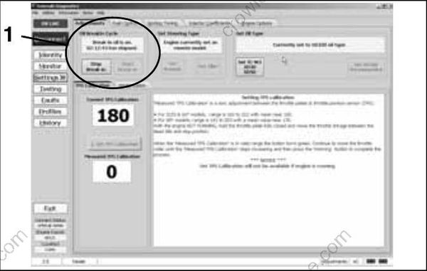
- Break-in oil setting
IMPORTANT: The operator must monitor the oil tank level to confirm oil consumption. This may require several hours of operation above idle speed.
