

COMPONENTS
Water Pump and Intakes
External water intakes mounted in the gearcase housing collect water and must supply the inlet side of the water pump with an unrestricted and unaerated water supply. Water is drawn into the water pump through a hole in the lower plate of the water pump assembly. All cooling water to the powerhead is provided by the water pump.
• A nylon wedge (impeller key) is used to engage the impeller bushing and driveshaft.
• The nylon impeller housing with liner must seal against a separate water pump plate.
• The bottom plate MUST seal to gearcase.
• The pump operates as a positive displacement pump at LOW speeds (below 1500 RPM) and as a centrifugal pump at HIGHER speeds.
Refer to WATER PUMP SERVICE on p. 274 for water pump servicing.
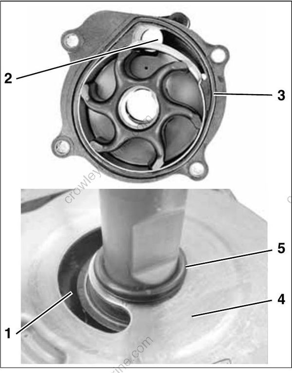
(Impeller key removed for clarity)
- Water inlet
- Water outlet
- Seal
- Plate
- O-ring
Water Supply Tube
The water pump outlet connects with the water supply tube located in the outboard’s midsection. Grommets seal the water tube to the water pump housing and the inner exhaust housing.
Water supplied to the water tube provides all cooling water to the adapter housing and cylinder block.
Adapter/Inner Exhaust Housing
• Adapts the cylinder/crankcase assembly (powerhead) to the exhaust housing and the water tube.
• Provides water passages which route incoming and outgoing cooling water.
• Provides exhaust passages which connect to the gearcase.
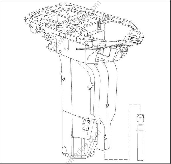
- Adapter housing
Pressure Relief Valve
A pressure relief valve is used to control water flow and operating temperature at higher speeds (above approximately 1800 RPM). The pressure relief valve opens as water pressure increases. Spring tension sets the opening pressure.
Overheating: A restricted or faulty valve typically results in HIGH SPEED overheating.
Overcooling: Debris may prevent the valve from closing completely.
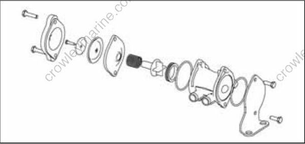
Pressure Relief Valve Components
Thermostats
Thermostats control water flow and operating temperature at lower speeds (below 1800 RPM).
Overheating: A restricted or faulty thermostat typically results in LOW SPEED overheating.
Overcooling: Debris may prevent the thermostat from closing completely.
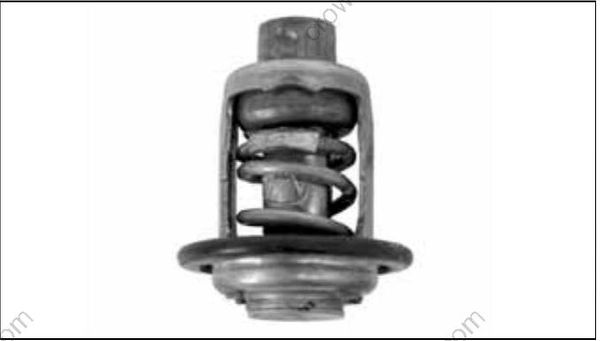
Thermostat
Block Venting
A fitting and hose from the top of the block allows the constant movement of water and/or air from the block. Circulated water flows through the EMM and Vapor Separator before exiting through the overboard indicator.
OPERATION
All models use a two-stage cooling system design. The cooling system is dependent on water pump pressure and controlled by thermostat and pressure valve operation.
IMPORTANT: Restricted or inadequate water flow through the outboard reduces cooling system performance and may lead to severe powerhead damage.
Cylinder Block / Cylinder Head Cooling
The flow of water through the cylinder block and cylinder heads is controlled by two thermostats and one external pressure valve. The pressure valve is connected by hoses to the top of each cylinder head.
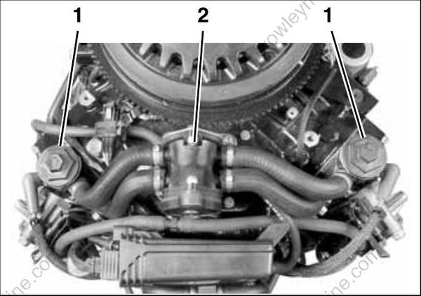
- Thermostats
- Pressure valve assembly
The thermostats and pressure valve control the flow of water entering the vertical water passages of the cylinder heads.
At low speed, the pressure valve is against the seat and the thermostats are closed. Warm water from the cylinder block gradually migrates to the thermostat pocket at the top of each cylinder head.
The thermostat opens when the water temperature reaches approximately 143°F (62°C).
