

ROUTINE INSPECTIONS
General
Check for external signs of fluid leakage. Correct causes as necessary.
Check the battery and make sure it is in good operating condition.
Reservoir Fluid
Check reservoir fluid level at least every three years or 300 operating hours. System capacity is approximately 15.2 fl. oz. (450 ml).
IMPORTANT: Use only Evinrude/Johnson Biodegradable TNT Fluid to fill the hydraulic system.
Refer to Trim and Tilt on p. 66 for filling procedure.
Manual Release Valve
Check the manual release valve with a torque wrench.
IMPORTANT: Tighten valve to a torque of 45 to 55 in. lbs. (5 to 6 N·m).
Stern Brackets
Inspect the stern brackets for binding.
Tighten starboard tilt tube nut to a torque of 45 to 50 ft. lbs. (61 to 68 N·m).
ELECTRICAL CIRCUIT TESTS
Relay Testing
When the trim-UP button is pressed, the UP relay is energized and connects the blue trim motor wire to the battery positive (+) terminal. The green trim motor wire remains grounded. When the button is released, the blue trim motor wire returns to a grounded position.
When the trim-DOWN button is pressed, the DOWN relay is energized and connects the green trim motor wire to the battery positive (+) terminal. The blue motor wire remains grounded. When the button is released, the green trim motor wire returns to a grounded position.
Refer to TILT/TRIM RELAY TEST on p. 130 for relay testing procedure.
Trim and Tilt Motor
Current Draw Tests
Careful analysis of the electric motor's current draw and trim/tilt unit operating speed aids evaluation of the electric motor and certain mechanical components.
Use a battery rated at 360 CCA (50 Ah) or higher that is in good condition and fully charged to perform this test.
IMPORTANT: Specifications are for static hydraulic tests. DO NOT attempt to perform the
following tests while the boat is moving.
Connect a 0 to 100 A DC ammeter in series between the battery side of the starter solenoid and the red lead to the trim/tilt relay module.
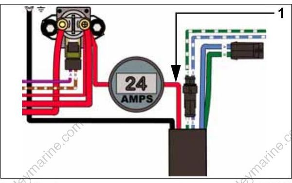
- Red lead 005441
Observe ammeter and a stopwatch while running hydraulic unit through several complete cycles. Compare test results to the values listed:
Observe ammeter and a stopwatch while running hydraulic unit through several complete cycles.
Compare test results to the values listed:
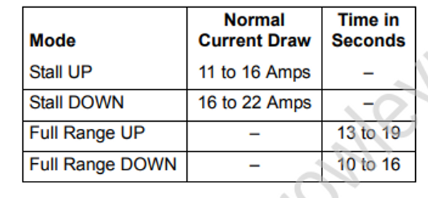
Test results include three basic possibilities:
A. Low current draw – Check for:
• Valves leaking
• Pump damaged
• O-rings leaking
B. High current draw – Check for:
• Pump binding
• Motor binding
• Valves sticking
• Relief valve springs damaged
C. Normal current draw, slow operating
speed – Check for:
• Damaged pump control piston
• Malfunctioning check valves
Trim and Tilt Motor No Load Test
IMPORTANT: Securely fasten motor in a suitable fixture before proceeding with this test.
Use a battery rated at 360 CCA (50 Ah) or higher that is in good condition and fully charged to perform this test.
Connect a 0 to 25 A ammeter in series with the battery positive (+) terminal, ammeter red lead toward terminal.
Attach or hold a vibration or mechanical tachometer to the motor while performing this test.
Monitor motor RPM and current draw.
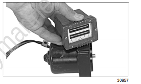
30957
The motor shaft must rotate clockwise, as viewed from the pump end, when positive (+) is applied to the blue lead, and negative (–) is connected to green lead.
The motor shaft must rotate counterclockwise, as viewed from the pump end, when positive (+) is applied to the green lead, and negative (–) is applied to the blue lead.
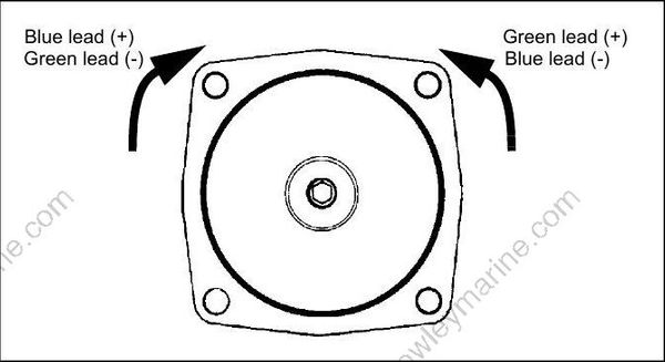
DR4238r
If test results vary, replace the motor.
Trim Gauge Test
STEP 1
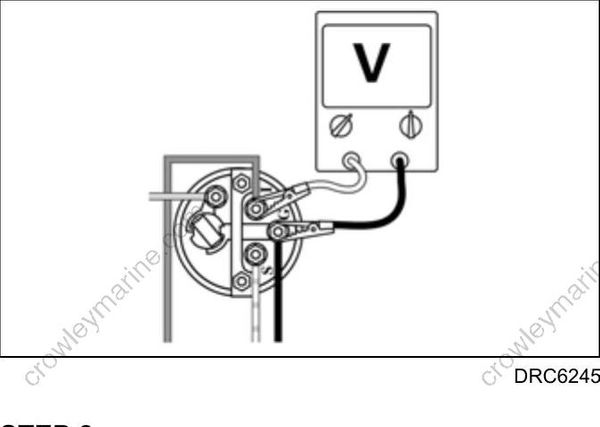
Turn key switch ON. Using a voltmeter, check for
voltage between the trim gauge “I” and “G” terminals.
• If no voltage, check condition of instrument harness, key switch, and engine 20 A fuse.
• If voltage is shown, go to STEP 2.
DRC6245
STEP 2
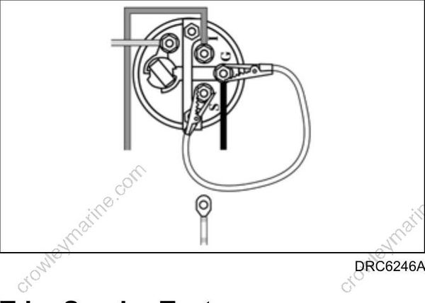
Remove the white/tan lead from the trim gauge “S” terminal. With key switch ON, gauge should
indicate full-trim DOWN position. Now connect a jumper wire between terminals “S” and “G.” Gauge should indicate full-trim UP position.
• If results are different, replace the trim gauge.
• If results agree, refer to Trim Sender Test.
DRC6246A
Trim Sender Test
IMPORTANT: To avoid immediate meter damage, never apply an ohmmeter to an electrical circuit where voltage is present.
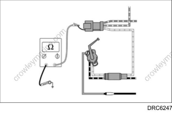
Disconnect the 3-pin Deutsch connector between the instrument harness and engine trim harness. Connect an ohmmeter between the white/tan wire, terminal “C,” of the engine harness and a clean engine ground.
With the outboard fully DOWN, meter must show a reading above 80 ohms. With the outboard fully UP, meter must show a reading below 10 ohms.
• If results agree, refer to Trim Gauge Test on p. 296.
• If results are different, replace trim sender.
DRC6247
