POWERHEAD
Use Gel Seal and Gasket Remover to remove all traces of gaskets, adhesives, and Gel-Seal II™ sealant from the cylinder block and crankcase.
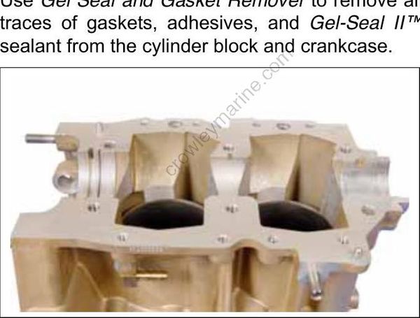
To avoid personal injury, wear eye protection and rubber gloves when using Gel Seal and Gasket Remover.
Carefully remove any carbon accumulation from the tops and ring grooves of the piston using Engine Tuner. A ring groove cleaning tool can be made by breaking an old ring and grinding an angle on its end. Do not damage ring grooves while cleaning.
Thoroughly wash entire cylinder block and crankcase with warm, soapy water to remove all traces of contaminants.
Air dry cylinder block and crankcase. Blow all holes and passageways with compressed air.
To avoid personal injury, wear eye protection and set compressed air pressure at less than 25 psi (172 kPa).
Cover the cylinder walls with a liberal amount of outboard lubricant to prevent corrosion.
POWERHEAD INSPECTION
For dimensions, refer to SERVICE SPECIFICATIONS on p. 10.
Before any inspection process can begin, all internal components must be completely clean and free of contaminants.
Visually inspect all parts. Check for unusual wear patterns, scuffing, or deterioration of aluminum parts, heat-related discoloration of bearings and bearing surfaces, and broken components.
Cylinder Head
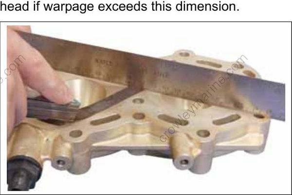
Check for cylinder head warpage using a piece of bar stock or machinist’s straightedge and a feeler gauge set.
Cylinder head warpage must not exceed 0.006 in (0.15 mm) per inch of measurement. Replace head if warpage exceeds this dimension.
Bearings
Inspect upper and lower main bearings for excess wear, nicks, or scratches. Replace if necessary.
Cylinder Bore
Use Cylinder Bore Gauge, P/N 771310, to inspect each cylinder bore for an out-of-round, oversize, or tapered condition. Be sure the gauge is perfectly square in the bore when measuring.
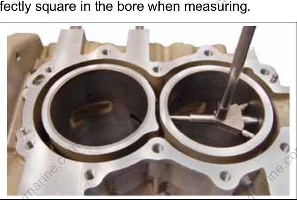
TYPICAL
Measure each cylinder in at least two areas. Each area should be measured twice. The difference between the two measurements in each area is the cylinder out-of-round dimension.
- The cylinder must not be out-of-round by more than 0.004 in. (0.10 mm).
The dimensional difference between the two areas is cylinder taper.
- The cylinder taper must not exceed 0.002 in. (0.05 mm).
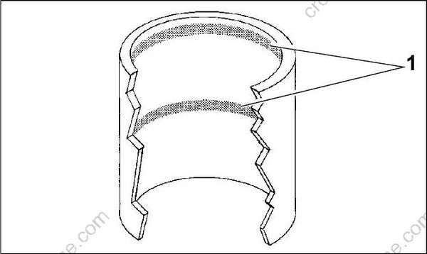
- Measurement areas
The difference between the measurements and standard bore is cylinder oversize. For dimensions, refer to SERVICE SPECIFICATIONS on p. 10.
- The cylinder must not be oversized by more than 0.003 in. (0.08 mm).
Pistons
Visually inspect pistons for signs of abnormal wear, scuffing, cracks, or burning.
Piston Rings
For new ring sets, place each ring separately in its respective bore. Use a piston to square the ring in the cylinder. Use a feeler gauge to measure the ring end gap.
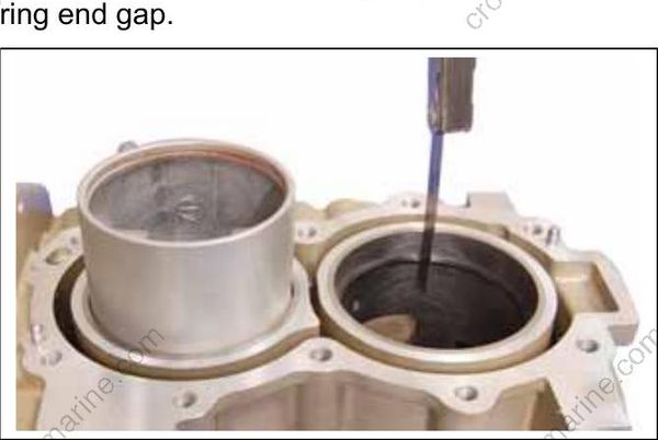
Ring end gap should be:
- 0.011 to 0.019 in. (0.30 to 0.50 mm)
Ring end gap increases approximately 0.003 in. (0.076 mm) for each 0.001 in. (0.025 mm) increase in cylinder bore diameter. DO NOT exceed cylinder oversize dimension.
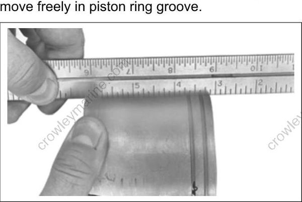
Use a machinist’s straightedge to check for proper ring clearance. Position piston rings on piston. Push rings into groove and hold straightedge against the side of the piston. Rings must be even or just below the surface of piston. Rings must move freely in piston ring groove.