

POWERHEAD DISASSEMBLY
General
To simplify reassembly and wiring installation, layout the various screws and clamps in the order of their proper location.
Remove the oil tank. Refer to Oil Tank Assembly on p. 181.
Remove fuel pump assemblies, filter and fuel injectors. Refer to FUEL COMPONENT SERVICING on p. 158.
Mark injectors for cylinder location before removal. All injectors must be installed in their original location. Improper injector installation can result in powerhead failure.
Remove ignition coils.
Remove the electric starter. Refer to Starter Removal on p. 136.
Remove EMM and electrical harness assembly. Refer to EMM SERVICING on p. 96.
Remove flywheel and stator. Refer to FLYWHEEL AND STATOR SERVICING on p. 133.
Remove throttle linkage. Refer to Throttle Linkage Removal on p. 198.
Remove shift linkage. Refer to Shift Linkage Removal on p. 198.
Remove the throttle body and reed plate assemblies. Refer to Intake Manifold Service on p. 165.
Remove thermostat and pressure valve assembly. Refer to THERMOSTAT AND PRESSURE RELIEF VALVE SERVICING on p. 190.
Remove oil supply and recirculation hoses.
Throttle Linkage Removal
Remove throttle cam and throttle lever.
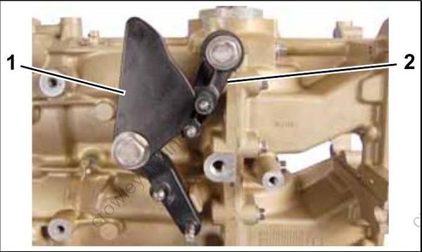
- Throttle cam
- Throttle lever
Shift Linkage Removal
Remove nut from shift lever. Remove shift lever and shaft assembly.

- Nut
Remove the ball, guide, and spring of the shift detent assembly from the crankcase.
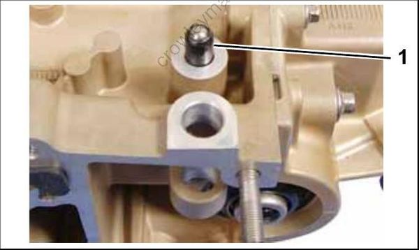
- Shift detent assembly
Cylinder Head Removal
Loosen in stages and remove cylinder head retaining screws. Remove the cylinder head. Discard cylinder head gasket.
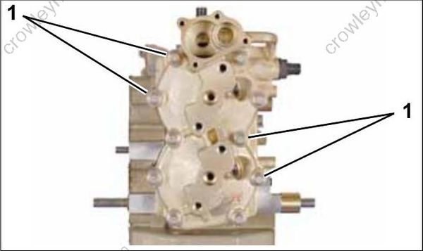
- Cylinder head screws (10 total)
Crankcase Disassembly
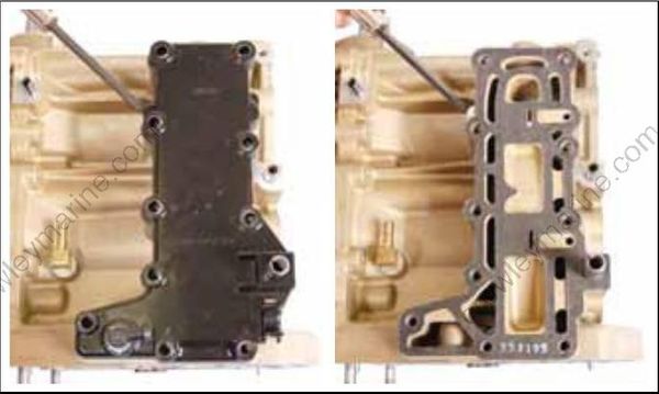
Remove screws and exhaust side water covers.
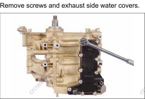
Use care to avoid bending or damaging inner exhaust side cover.
Remove crankcase flange screws. Loosen in stages and remove the main bearing screws.
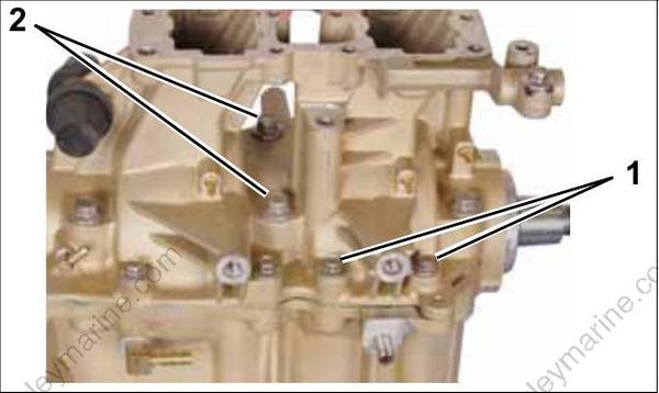
- Flange screws
- Main bearing screws
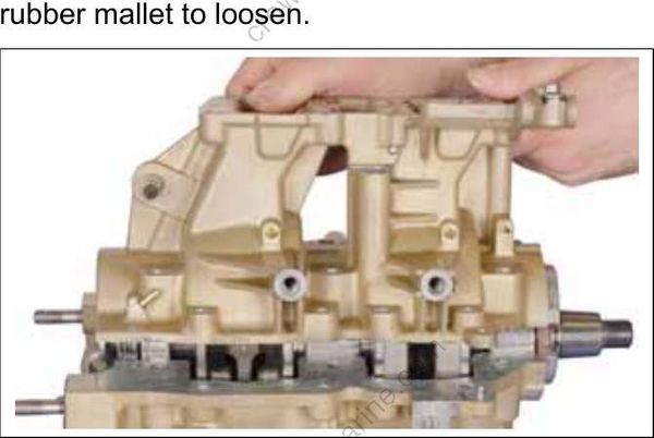
Separate crankcase and cylinder block. It may be necessary to tap on crankshaft with a rawhide or rubber mallet to loosen.
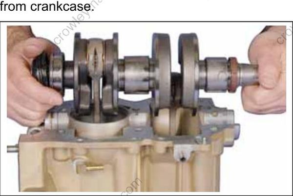
Crankshaft Assembly Removal
Carefully lift crankshaft straight up and remove from crankcase.
Connecting Rods and Pistons
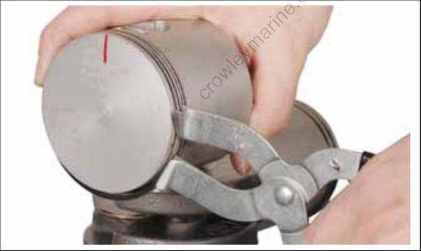
Use an appropriate ring expander to remove all piston rings from pistons. Discard the rings.
Wear safety glasses to avoid injury.
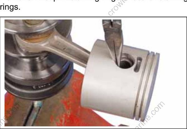
Remove wrist pin retaining rings. Discard retaining rings.
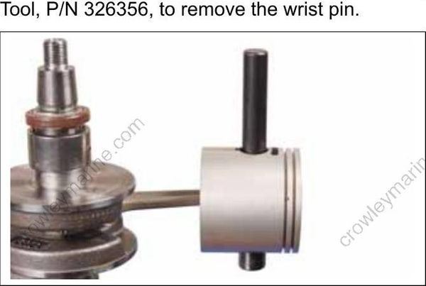
The wrist pin fit is loose on both sides. Push the wrist pin through to free the piston from the connecting rod. If necessary, use Wrist Pin Pressing Tool, P/N 326356, to remove the wrist pin.
Crankshaft
Remove upper seal from crankshaft. Discard the seal. A new upper seal must be installed on assembly.
Remove the upper main bearing.
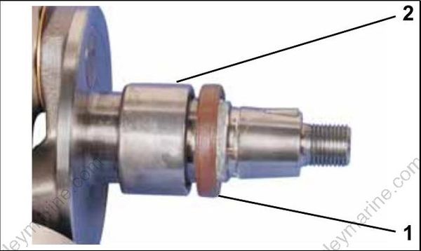
- Upper oil seal
- Upper main bearing
Remove the lower bearing seal housing.
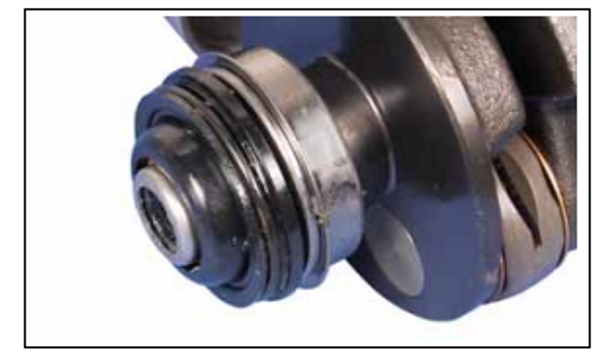
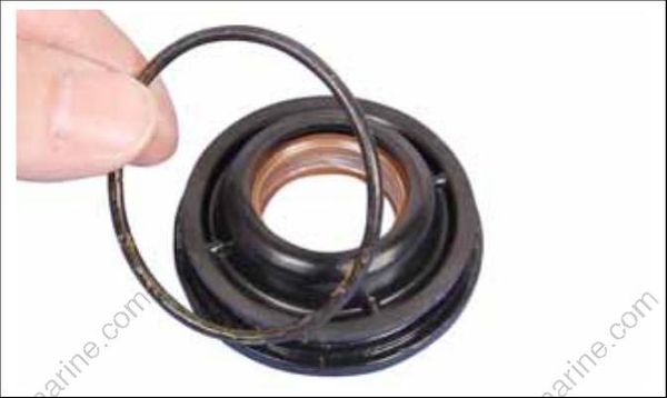
Remove the housing O-ring. Discard O-ring.
Use a punch to remove the housing seal. Discard seal.
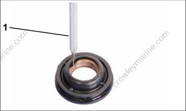
- Punch
Inspect housing and replace if necessary.
Remove O-ring from crankshaft sleeve and inspect it. Replace the O-ring if it is not in good condition.
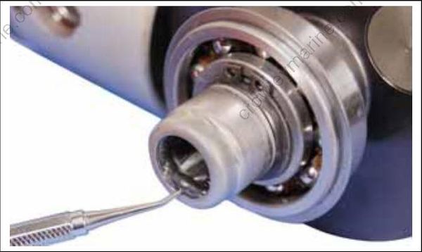
Inspect the crankshaft sleeve and replace if necessary. To remove the sleeve, use Slide Hammer, P/N 432128, and Puller Jaws, P/N 432130.
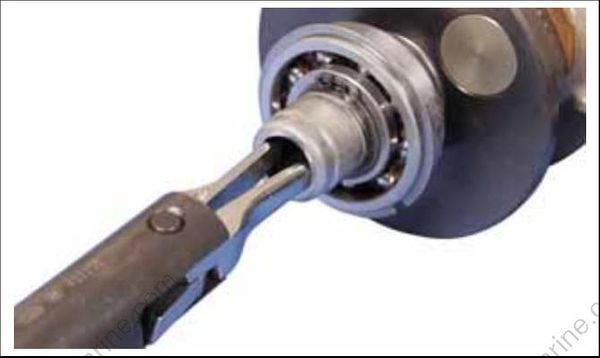
CYLINDER BLOCK CLEANING
Remove the lower main bearing only if it needs to be replaced. Use external retaining ring pliers to remove the lower bearing retaining ring.
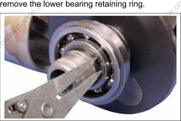
If the lower main bearing is removed from the crankshaft, it must be discarded. DO NOT reuse it.
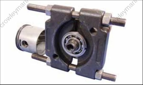
Use a bearing separator to support the bearing, and press off the crankshaft.
CYLINDER BLOCK CLEANING
Before inspecting or assembling powerhead, all internal components must be completely clean and free of contaminants.
Remove any carbon accumulation from exhaust port areas.
Remove any carbon accumulation from cylinder head combustion chambers.
If cylinder walls are glazed from extended use, use a rigid, medium grit cylinder hone to resurface walls. Use slow RPM for best oil retention and ring sealing. When finished, a cross hatch pattern of 22 to 32° should be visible in the cylinder wall. The pattern should be uniform in both directions.
To avoid piston or cylinder block damage, restore the chamfer to all port edges using a ball hone or other suitable tool.
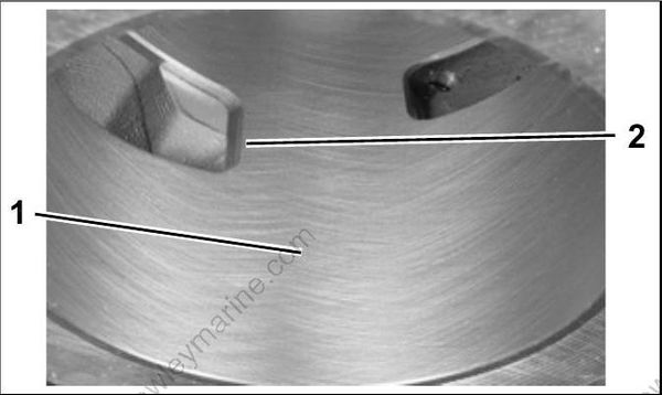
- Crosshatch pattern in cylinder wall
- Chamfered port edge
