

MIDSECTION
Apply Triple Guard grease to both sides of thrust washer. Install thrust washer on steering arm.
Install lower mount bracket on steering arm.
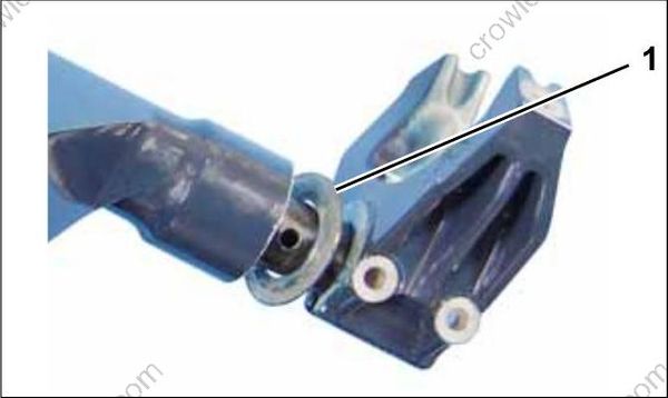
- Thrust washer
Install lower mount retaining screws. Tighten screws to a torque of 10 to 12 ft. lbs. (14.5 to 16.5 N-m).
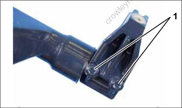
- Retaining screws
Install exhaust housing. Refer HOUSING SERVICE on p. 226.
Install tiller handle. Refer to TILLER HANDLE SERVICE on p. 249.
Adjust tiller steering friction. Refer to Steering Friction Adjustment on p. 266.
TILLER HANDLE SERVICE
Removal
To avoid accidental starting of engine while servicing, twist and remove all spark plug leads.
Remove lower engine covers. Refer to .
Disconnect tiller electrical connector, touch troll connector and trim connector, if equipped.
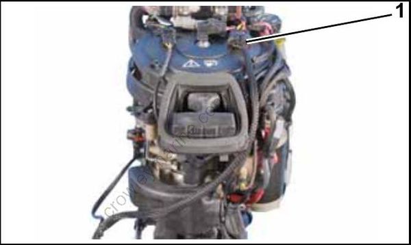
- Tiller electrical connector
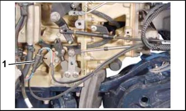
- Touch troll connector
Remove neutral switch and bracket.
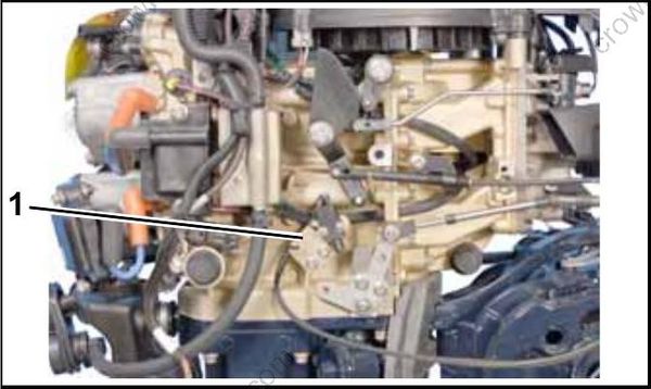
- Neutral switch and bracket
Use Ball Socket Remover Tool, P/N 342226, to remove throttle cable connector from throttle lever. Remove screw and washer from throttle cable retainer.
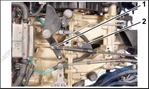
- Throttle cable connector
- Throttle cable retainer
Remove clip and washer from shift lever pin and remove shift cable connector from shift lever pin.
Remove cable anchor screw and washer from shift cable retainer.
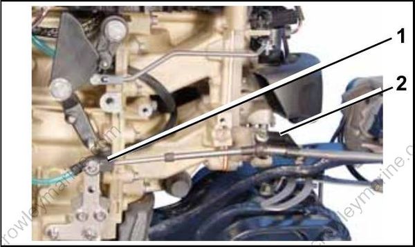
- Shift cable connector
- Shift cable retainer
Remove locknuts from screws on bottom of steering arm.
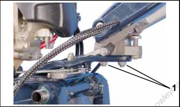
- Locknuts
Remove front steering handle screw and washer.
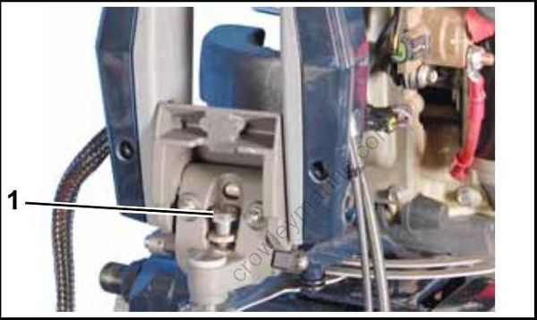
- Front steering arm screw and washer
Remove rear steering handle screw and washer.
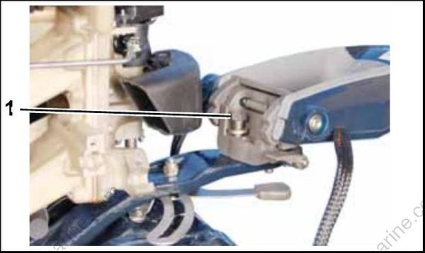
- Rear steering arm screw and washer
Remove tiller handle assembly.
Disassembly
Loosen throttle friction control so there is no restriction on grip.
Do not back screw out completely. Nut is under spring tension.
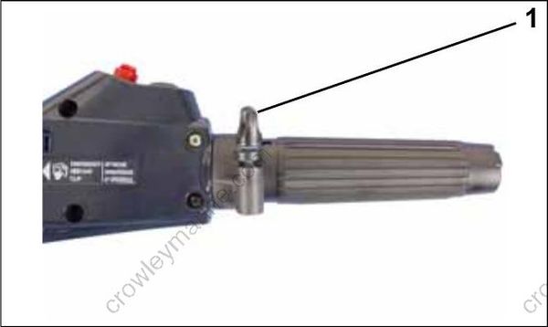
- Throttle friction control
Remove eight screws and bottom cover of tiller handle.
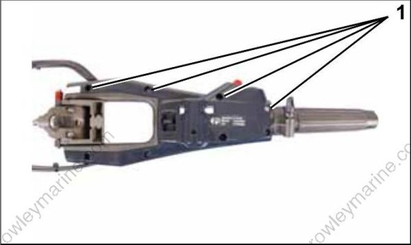
- Cover screws
Remove shift handle screw and shift handle.
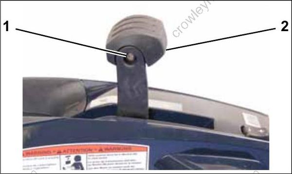
- Screw
- Shift handle
Remove stop switch screws. Loosen start switch nut.
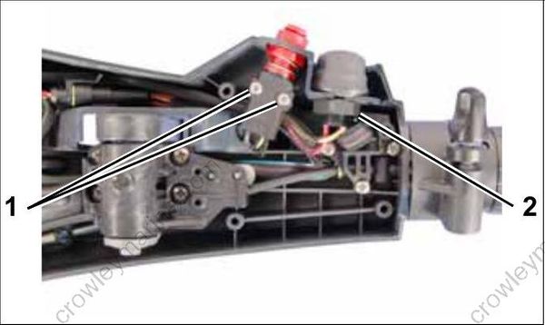
- Screws
- Start switch nut
Remove start switch, stop switch, housing, spring, button, and spacer.
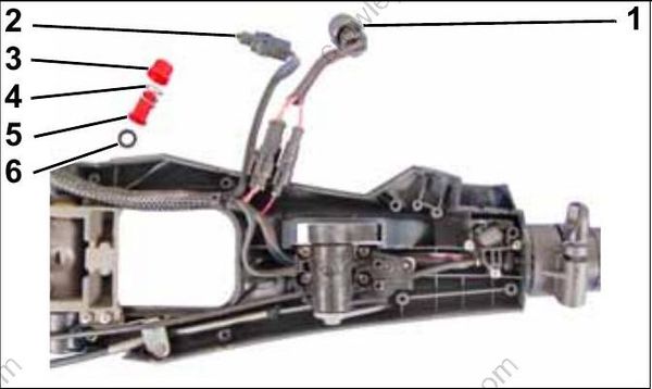
- Start switch
- Stop switch
- Housing
- Spring
- Button
- Spacer
Disconnect start switch connectors. If replacing trim switch, remove tie straps from harness and remove connectors from trim switch wires. Refer to CONNECTOR SERVICING on p. 141.
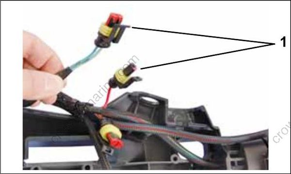
- Trim switch wire connectors
Remove shift cable retainer.
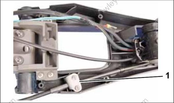
- Shift cable retainer
Remove screw and washer from shift link.
Remove shift cable and shift link.
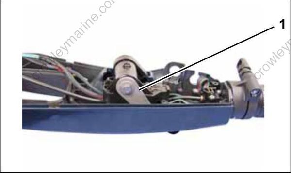
- Shift link
Remove cotter pin from shift link and remove shift cable.
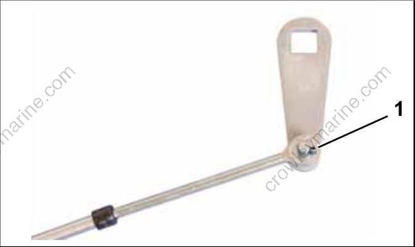
- Cotter pin
Remove four shift lever bracket retaining screws.
Remove shift lever bracket.
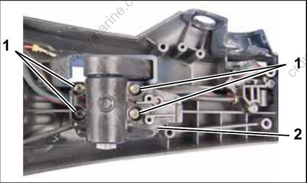
- Screws
- Shift lever bracket
Remove two shift detent retaining screws.
Remove detent spring.
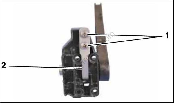
- Screws
- Shift detent spring
Remove shift lever from shift bracket.
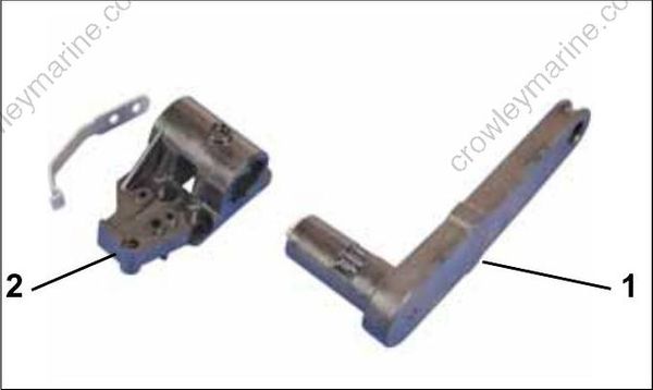
- Shift lever
- Shift bracket
Remove the Touch Troll switch bracket retaining screws. Remove the Touch Troll switch and bracket.
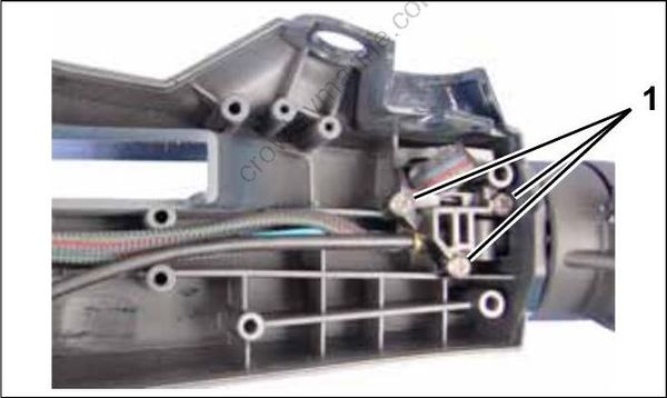
- Screws
Use Twist-Grip Remover, P/N 390767, to depress the grip detents. Tighten screw and remove the grip by pulling grip.
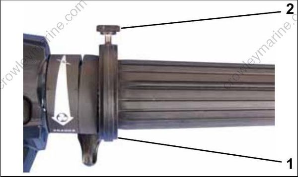
- Twist-Grip Remover
- Screw
Remove the helix halves, rollers, and guides
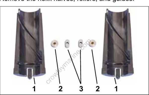
- Helix halves
- Rollers
- Guides
Pull the throttle pin out of the cable.
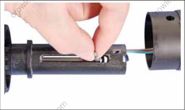
Remove the throttle cable.
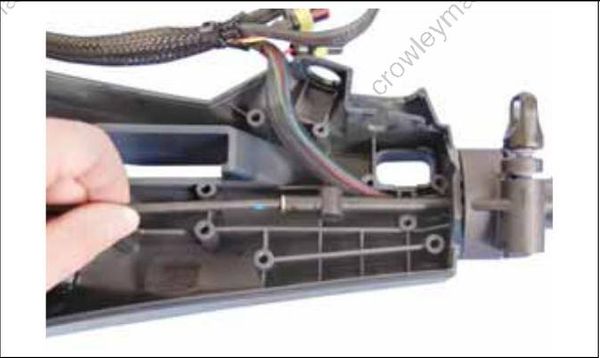
The twist grip and trim switch wiring can now be removed from the inner handle.
Use an appropriate tool to carefully pry the trim switch out of the twist grip.
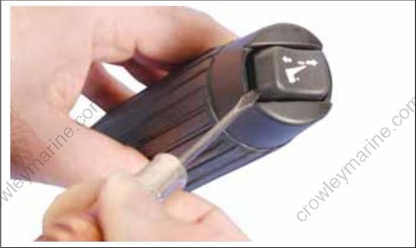
Remove the throttle friction control.
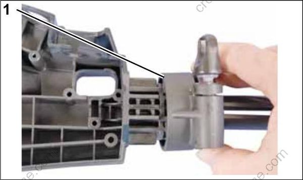
- Throttle friction control
Remove nut, washer and bushing from port side of tiller handle.
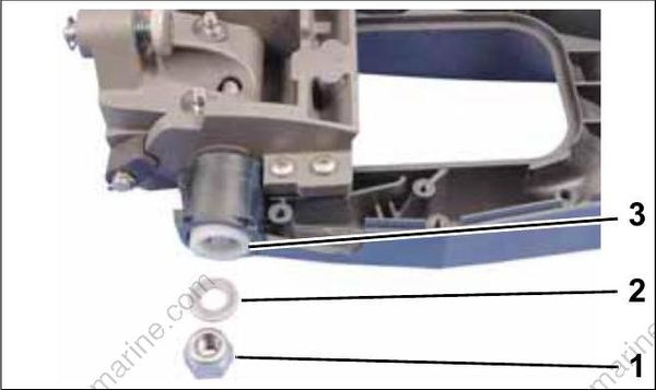
- Nut
- Washer
- Bushing
Remove steering handle screw.
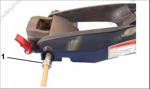
- Steering handle screw
Remove base from tiller handle. Remove two bushings from base.
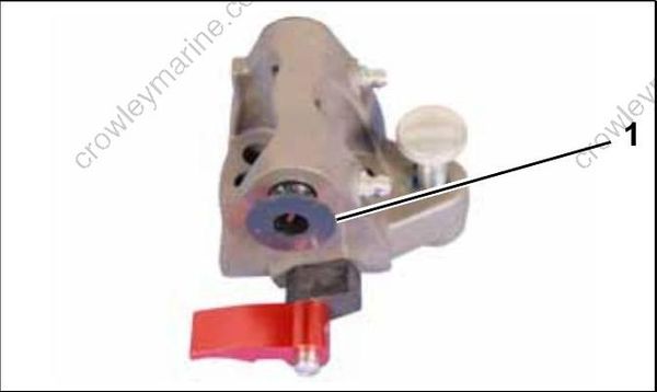
- Bushing
If replacing tilt detent pawl, tilt release lever, tilt detent pin or spring, remove cotter pin and roll pins as needed.
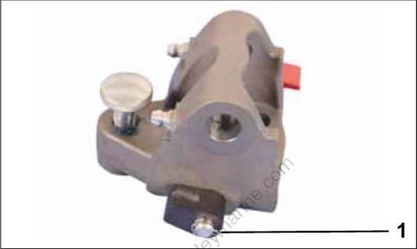
- Cotter pin
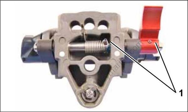
- Roll pins
Remove four screws and bushing from bracket.
Remove bracket from handle.
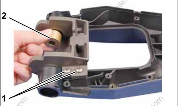
- Screws
- Bushing
Inspection
Inspect the throttle cable for kinks and wear. Replace if necessary.
Inspect the shift cable for kinks and wear. Replace if necessary.
Inspect the steering handle components for wear, cracks, or damage. Replace parts if necessary.
Refer to Emergency Stop Switch Test on p. 129 to test stop switch.
Assembly
Install bracket on handle. Install four screws. Tighten screws securely and install bushing in bracket.
When reinstalling screws in composite materials turn screws COUNTER-CLOCK-WISE until threads of screw engage threads of screw boss.
Failure to follow this procedure will damage the screw boss threads. Once threads are engaged, tighten screws securely.
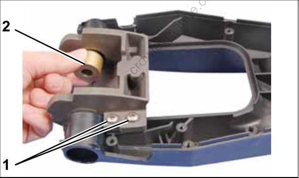
- Screws
- Bushing
Install tilt detent pawl on tilt detent pin. Secure with new cotter pin.
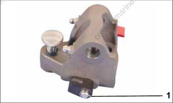
- Cotter pin
Install two bushings in base.
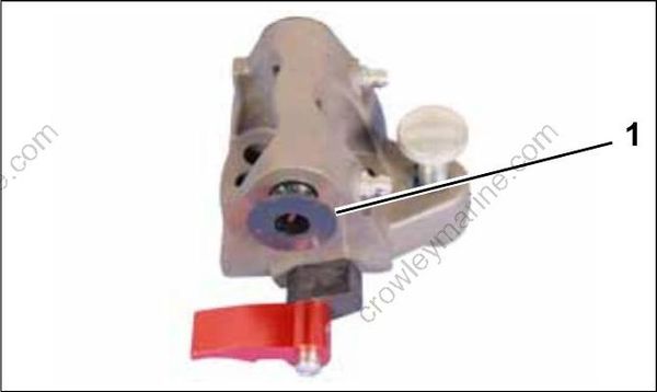
- Bushing
Hook spring to roll pin and recess in base as shown. Turn tilt release lever one turn to apply tension to the spring. Hold lever in position and install base in bracket.
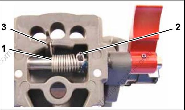
- Spring
- Roll pin
- Recess
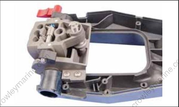
Make sure spring returns tilt release lever.
Use an appropriate tool to align screw hole through the tiller handle, bracket and base. Install steering handle screw. Tighten screw so tiller handle pivots easily. Refer to Tiller Handle Friction on p. 267.
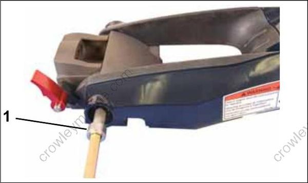
- Steering handle screw
Install bushing, washer and nut on port side of tiller handle. Tighten nut to a torque of 25 to 28 ft. lbs. (35 to 38 N-m).
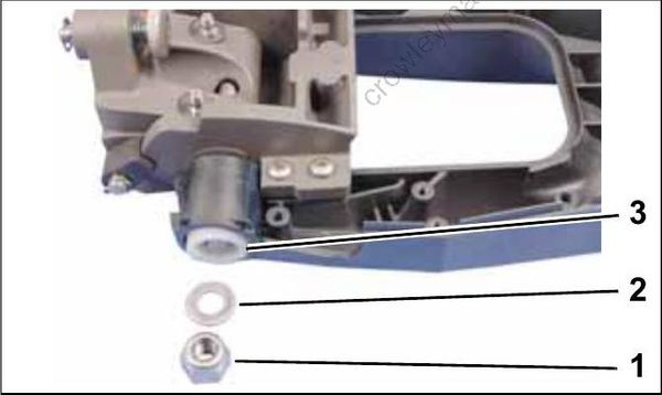
- Nut
- Washer
- Bushing
Install the throttle friction control.
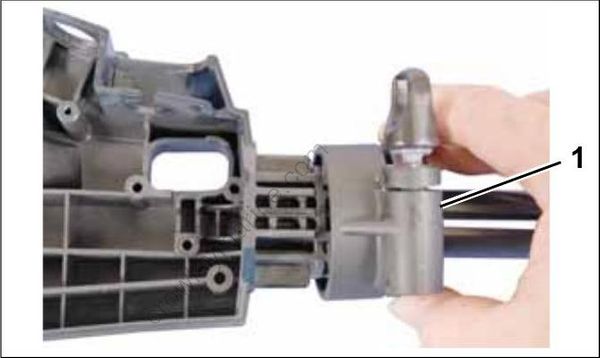
- Throttle friction control
Press the trim switch into the twist grip. Be sure trim switch UP position aligns with the twist grip indicator line as shown.
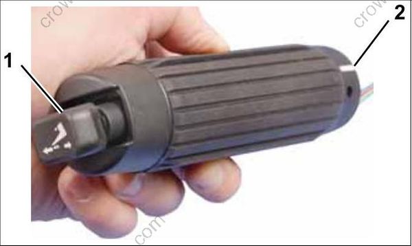
- Trim switch UP position
- Indicator line
Install trim switch wiring through inner steering handle.
Trim switch wiring must NOT be twisted through the throttle twist grip or inner tiller handle / wire guide.
Insert wire guide into inner steering handle.
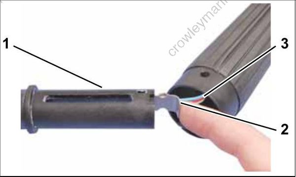
- Inner tiller handle
- Wire guide
- Trim switch wires
Push wire guide into place until locking tab is in place as shown.
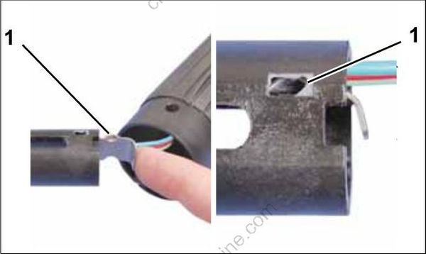
- Locking tab
Wire guide should slide easily into place. If any binding is felt, inspect trim switch wiring for twisting. If wire guide is forced into place, it WILL damage trim switch wiring.
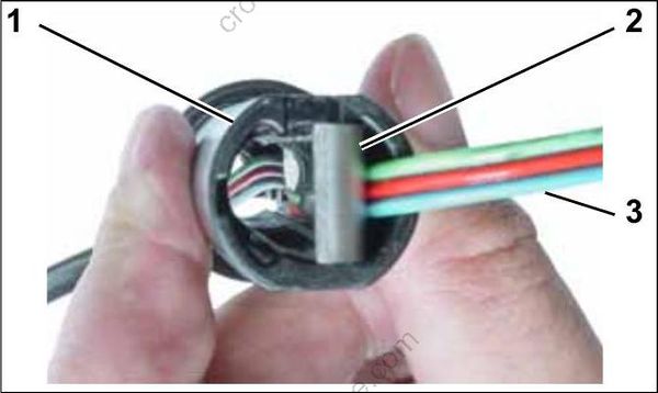
- Inner tiller handle
- Wire guide
- Trim switch wires
Make sure trim switch wiring is NOT twisted before proceeding.
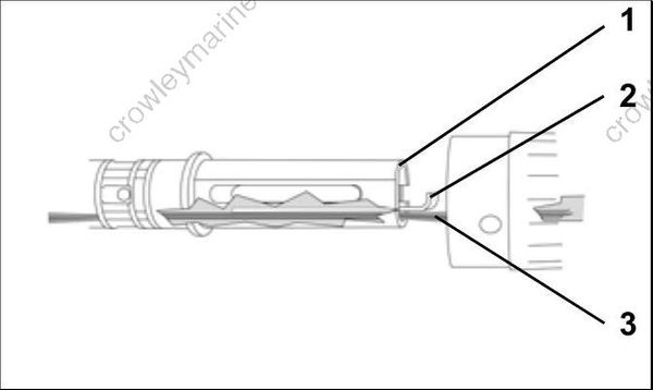
- Inner tiller handle
- Wire guide
- Trim switch wires
Install the throttle cable.
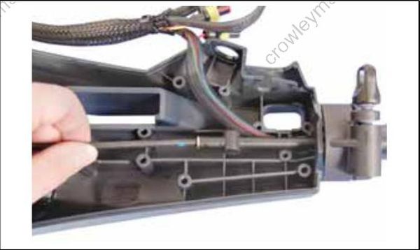
Install the throttle pin in the cable.
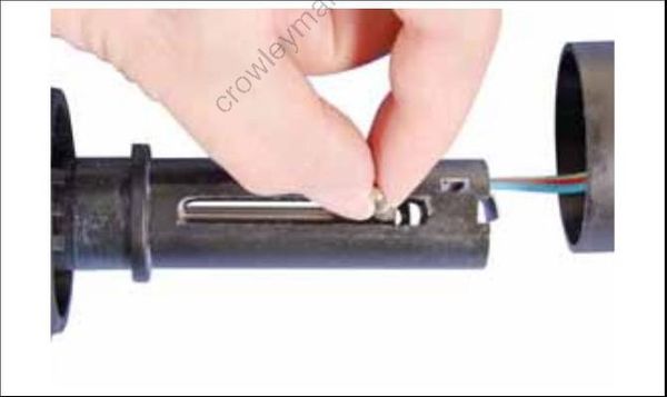
Apply Lubriplate to the ends of pin, guides, rollers, helix grooves and inner handle guide slot. Place the guides over the roller pin and into the slots of the inner handle. Place the rollers on the ends of the roller pin.
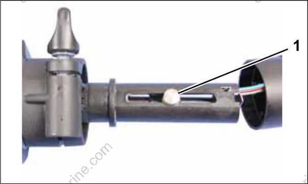
- Roller
Assemble the helix halves on the handle and slide the grip over the helix.
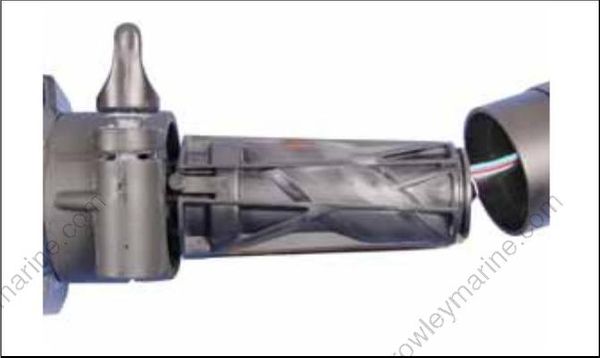
Carefully pull trim switch wires through inner tiller handle as twist grip assembly is installed.
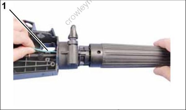
- Trim switch wiring
Be sure the twist-grip's speed indicator line is positioned with the speed range symbol on the handle. Snap the grip into place.
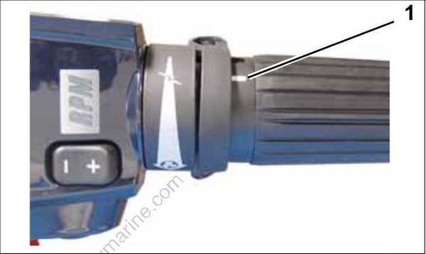
- Indicator line
Place trim switch wiring under throttle cable as shown.
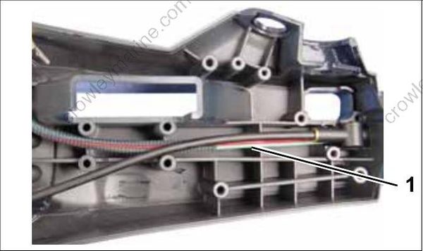
- Trim switch wiring
Place Touch Troll wiring under throttle cable as shown. Install touch troll switch bracket with three screw. Tighten screws securely.
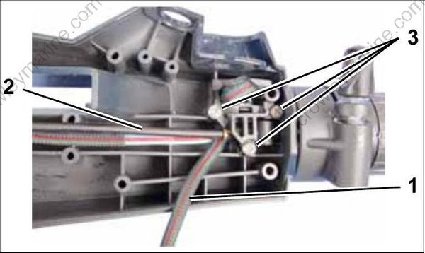
- Wiring
- Throttle cable
- Screws
Route wiring under throttle cable as shown.
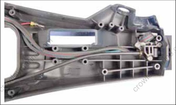
Install shift cable on shift link. Secure with a new cotter pin.
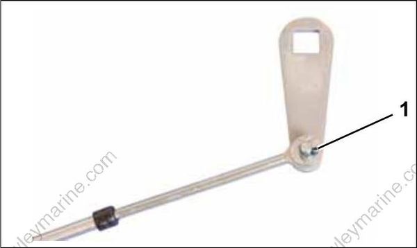
- Cotter pin
Apply Lubriplate to the shaft portion of shift lever. Install shift lever into shift bracket. Install the detent spring with two shift detent retaining screws. Tighten screws securely.
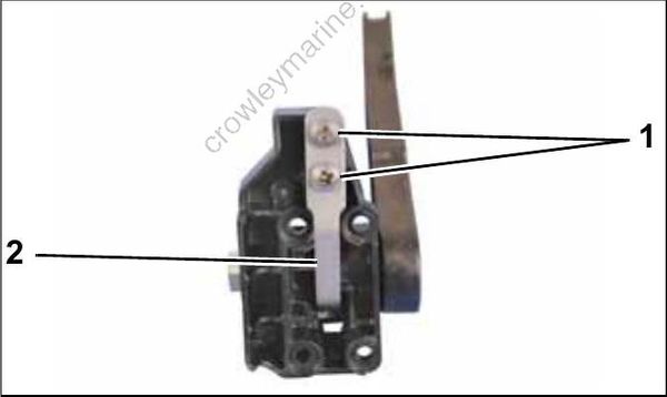
- Screws
- Shift detent spring
Install shift lever assembly. Install four shift lever bracket retaining screws. Tighten screws securely.
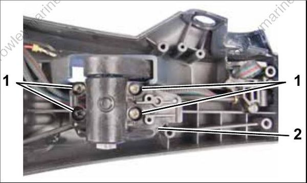
- Screws
- Shift lever bracket
Install shift link and cable on shift lever. Apply Ultra Lock to threads of screw and install washer and screw. Tighten screw to a torque of 84 to 106 in. lbs. (9.5 to 12 N-m).
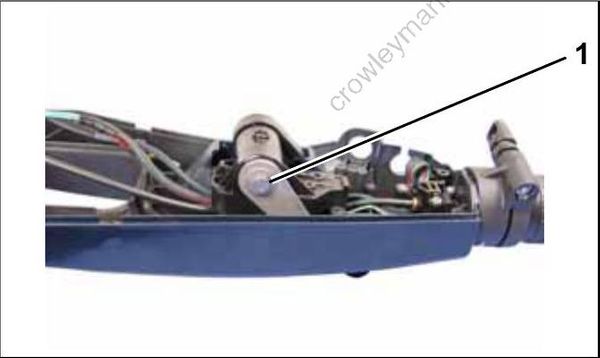
- Screw and washer
Install shift cable retainer with two screws. Tighten screws securely.
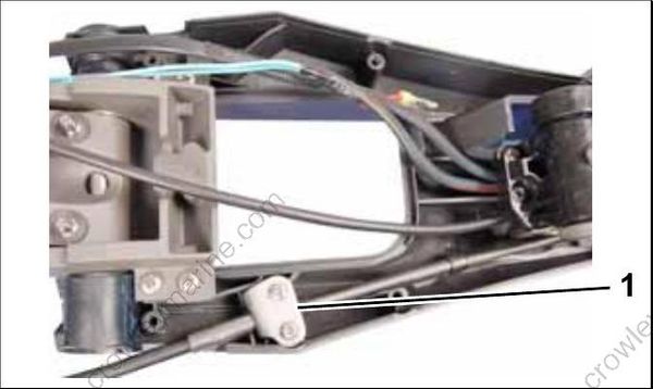
- Shift cable retainer
If trim switch was removed, install tie straps on harness. connectors.
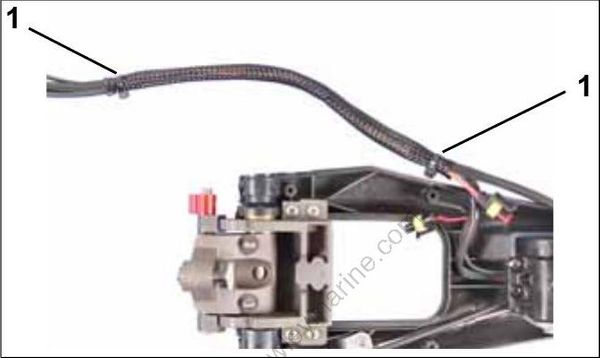
- Tie straps
Install connectors on trim switch wires. Refer to CONNECTOR SERVICING on p. 141. Connect start switch connectors.
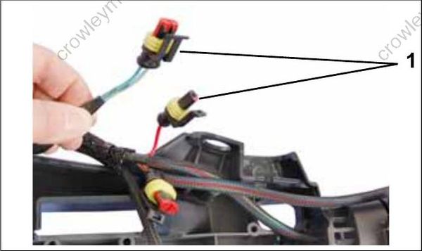
- Trim switch connectors
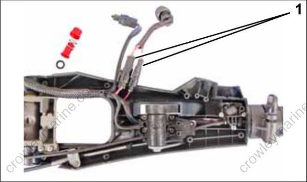
- Start switch connectors
Install start switch. Tighten start switch nut securely. Install stop switch housing, spring, button and stop switch. Secure with two screws. Tighten screws securely.
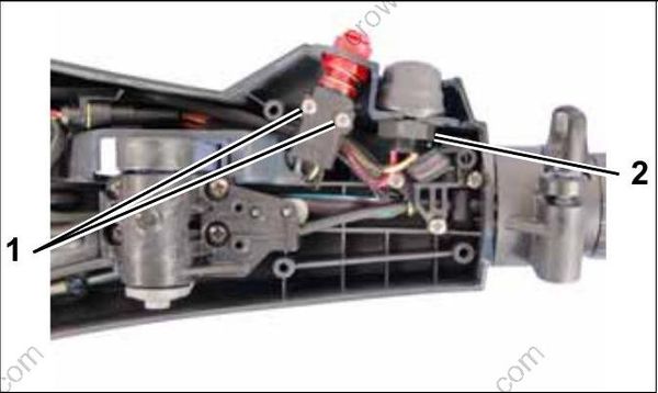
- Screws
- Start switch nut
Route shift and throttle cables, and wiring harness as shown.
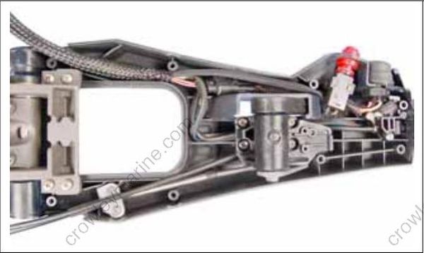
- Screws
- Start switch nut
Install bottom cover of tiller handle with eight screws. Tighten screws securely.
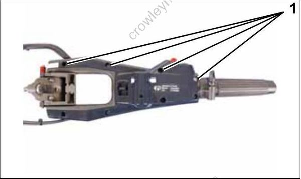
- Cover screws
Install shift handle. Install shift handle screw. Tighten screw securely.
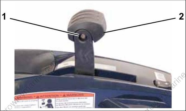
- Screw
- Shift handle
Installation
Place tiller bracket on steering arm.
Install screw and washer in front mounting hole.
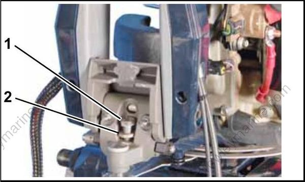
- Screw
- Washer
The tiller handle angle can be set to center or angled to port or starboard 20° .
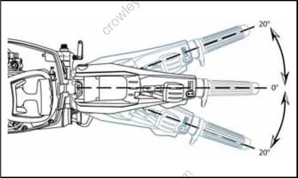
Install rear washer and screw in appropriate location.
Tighten both screws to a torque of 18 to 20 ft. lbs. (25 to 27 N-m).
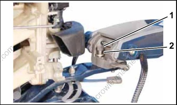
- Screw
- Washer
Install locknuts on screws.
Hold screws with a wrench and tighten locknuts to a torque of 18 to 20 ft. lbs. (25 to 27 N-m).
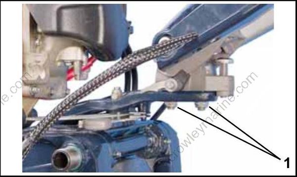
- Locknuts
Control Cable Installation
Make sure throttle and shift cable ends are fully seated.
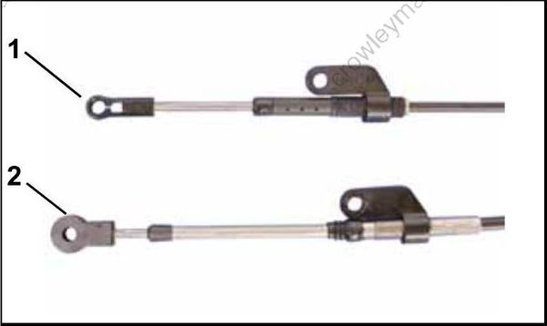
- Throttle cable end
- Shift cable end
Do NOT use threaded cable ends to make cable adjustments.
Secure shift cable to the shift lever pin.
For proper installation, review the following steps:
- Place washer on pin.
- Position retainer clip with straight section on the bottom and angled section on the top.
- Use long nose pliers to insert straight section of clip into linkage pin hole.
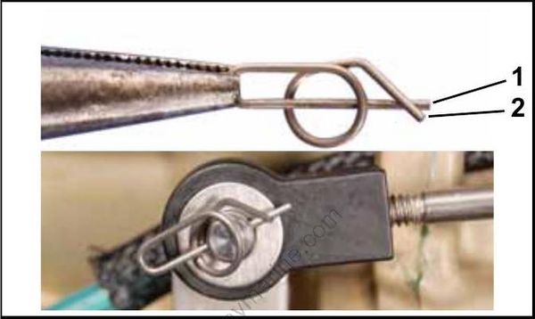
- Straight section
- Angled section
Push the clip towards the hole while lifting on the curved end with the pliers.
Be sure retainer clip fully engages the pin.
Lock the retainer by moving the angled section behind the straight section.
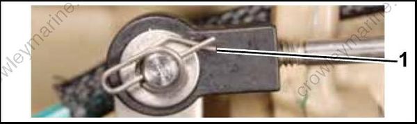
Locked Retainer Clip
- Angled section behind straight section
Pull firmly on shift cable casing to remove backlash.
With outboard and shift lever in NEUTRAL, place shift cable on the trunnion bracket of intake manifold as shown. Rotate the anchor to align.
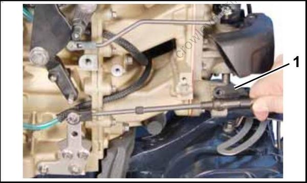
- Anchor
Install washer between anchor and trunnion bracket. Install screw. Tighten screw to a torque of 84 to 106 in. lbs. (9.5 to 12 N-m).
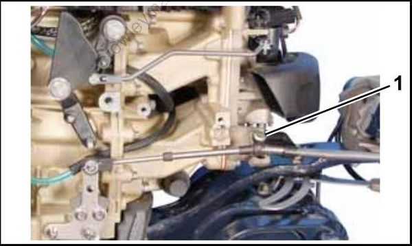
- Screw
Install throttle cable connector with Ball Socket Installer tool, P/N 342225.
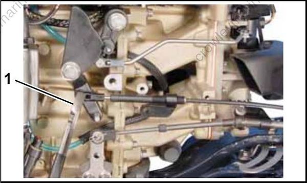
- Installer tool, P/N 34222
Place throttle cable through upper trunnion pocket.
Hold twist grip in IDLE position. Pull firmly on cable to remove backlash.
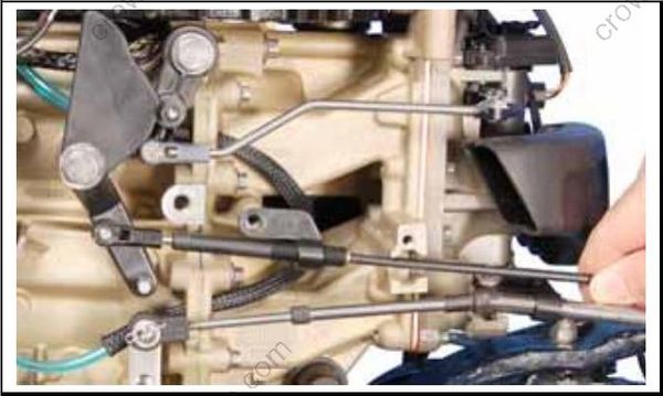
Adjust cable anchor so throttle cam is against IDLE stop when anchor screw hole aligns with screw boss on block.
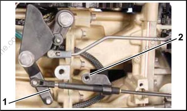
- Idle stop
- Anchor aligned with screw hole
Rotate anchor one additional turn toward the end of the cable.
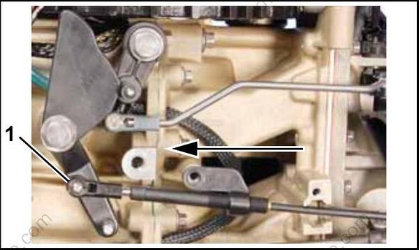
- End of cable
Install washer between anchor and boss. Install screw. Tighten screw to a torque of 84 to 106 in. lbs. (9.5 to 12 N-m).
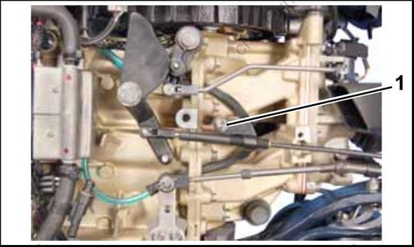
- Cable anchor screw
Rotate twist grip. Make sure throttle cam goes to full throttle without overloading cable, and still returns to IDLE stop.
Turn propeller shaft and shift outboard to FORWARD.
Route neutral switch wiring as shown.
Install bracket to block. Tighten screws to a torque of 35 to 60 in. lbs. (4 to 6.8 N-m).
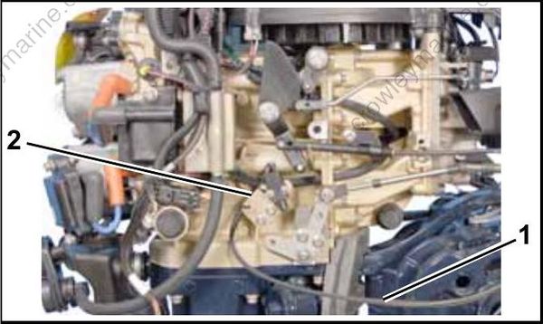
- Neutral switch wire routing
- Bracket
Route touch troll wiring as shown. Secure retainer to water hose as shown.
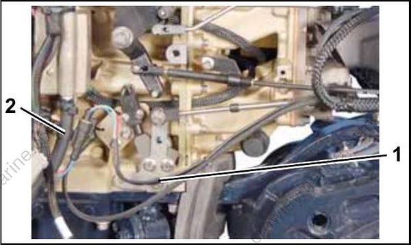
- Touch troll wire routing
- Retainer
Route tiller control wiring as shown.
Connect tiller electrical connector. Secure to retainer on starter housing.
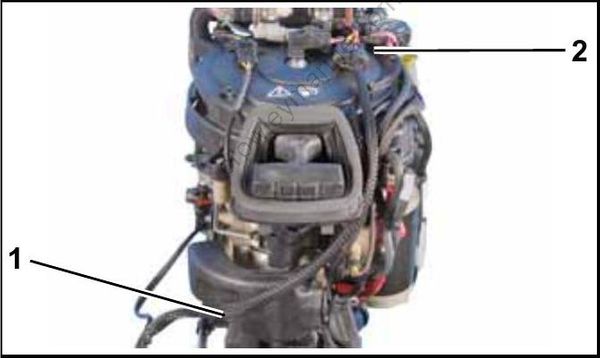
- Wire routing
- Retainer
Place battery cables and trim wiring through hole in port lower motor cover.
Route trim wiring as shown.
Connect electrical connector and use tie strap to secure as shown.
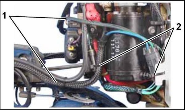
- Wire routing
- Secure with straps
Install lower motor covers. Refer to Lower Cover Installation on p. 75.
Before returning outboard to customer, check:
- Start switch
- Engine stop circuit
- Emergency stop switch and lanyard
- Steering movement
- Friction control
- Throttle control (IDLE to WIDE OPEN)
- Touch Troll operation
- Shift control and proper gear engagement
- Start-in-gear protection
- Trim and tilt control
