

BOAT RIGGING
Remote Controls
Control Selection
The remote control used must have startin-gear prevention. This feature can prevent injuries resulting from unexpected boat movement when the outboard starts.
Remote control and wiring harness options are described in the Evinrude/Johnson Genuine Parts and Accessories Catalog.
The remote control and wiring harness combination must have the following features:
- Start-in-gear prevention
- Emergency stop / key switch
- Shift stroke must measure 1.125 to 1.330 in. (28.6 to 33.8 mm) between NEUTRAL and FORWARD
- Throttle stroke must PUSH for open.
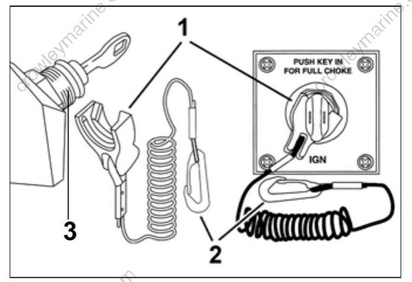
- Emergency stop clip
- Safety lanyard
- Key switch with emergency stop feature
Always install and recommend use of an emergency stop/key switch. Doing so will reduce the risk of personal injury or death should the operator fall away from the controls or out of the boat.
Control Installation
Plan the installation of remote controls carefully, following all instructions provided with the remote control.
Make sure the following items are checked:
- Correct length, type and quality of control cables and wiring harnesses
- Proper routing of cables and harnesses
- Slack in front of the outboard for remote control cables
- Positioning and securing of cables and harnesses along their lengths to prevent movement or damage.
Typical transom-mounted outboard installations require a 12 in. (30 cm) cable loop at the front of the outboard when the cables are routed from the side of the splash well.
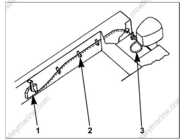
- Surface side-mount remote control
- Cable support
- 12 in. (30 cm) cable loop at front of outboard
IMPORTANT: Cables of the proper length, style, and quality that are correctly installed and adjusted will eliminate most control-related operational problems.
Battery Installation
Each outboard requires its own starting battery. Select a battery that meets or exceeds the minimum requirements.
Minimum 12 Volt Battery Recommendations
| Outboard Model | Battery Rating |
|---|---|
| 25–30 HP | 640 CCA (800 MCA), or 800 CCA (1000 MCA) below 32° F (0° C)107 amp-hr in extreme applications |
Location and Preparation
Proper installation will prevent battery movement while underway.
- Secure all batteries in protected locations.
- Place battery as close to the outboard as possible.
- Battery location must provide access for periodic maintenance.
- Use battery mounting trays or battery boxes on all battery installations.
- Connections and terminals must be covered with an insulator.
- Battery connections must be clean and free from corrosion.
- Read and understand the safety information supplied with the battery before installation.
Keep the battery connections clean, tight, and insulated to prevent their shorting or arcing and causing an explosion. If the battery mounting system does not cover the connections, install protective covers. Check often to see that connections stay clean and tight.
Connections
IMPORTANT: Connect the battery positive (+) cable to the battery positive (+) post FIRST. Connect the battery negative (–) cable to the battery negative (–) post LAST.
Install a starwasher on the threaded battery post. Stack cables from the outboard, then cables from accessories. Finish this connection with a hex nut.
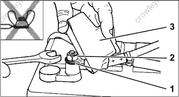
Marine Style Battery Post
- Starwasher
- Hex nut
- Terminal Insulator
IMPORTANT: Do not use wing nuts to fasten ANY battery cables. Wing nuts can loosen and cause electrical system damage not covered under warranty.
Tighten all connections securely. Apply Triple-Guard grease to prevent corrosion.
Battery Cable Requirements
Evinrude outboards are shipped with stranded copper battery cables for typical installations in which the starting battery is positioned close to the transom.
Specialized outboard installations with extended length battery cables require an increased wire size. Refer to the following table.
| 25–30 HP | |
|---|---|
| 1 to 10 Ft.(.3 to 3 m) | 6 Gauge |
| 11 to 15 Ft.(3.4 to 4.6 m) | 4 Gauge |
| 16 to 20 Ft.(4.9 to 6.1 m) | 2 Gauge |
IMPORTANT: Inadequate battery cables can affect the performance of an outboard’s high amperage start circuit and the cranking speed of the outboard. DO NOT use aluminum wire cables. Use ONLY AWG stranded copper wire cables.
Battery Switches and Multiple Batteries
A multiple battery setup, including marine battery selector switches, can provide flexibility in single and dual outboard installations.
Refer to Battery and Switch Wiring Diagrams on p. 28 for battery connection options.
The battery selection function can be used for emergency starting if a primary battery becomes discharged.
The OFF position of the battery selector switch can be used to minimize battery discharge during periods of non-use.
Typical battery functions
IMPORTANT: Never connect an external battery isolator to the stator of an Evinrude E-TEC.
Primary
- Used as starting battery under normal operating conditions.
- Red (+) cable connected to battery selector switch.
- Primary battery is charged by connection to main red (+) outboard battery cable.
Dual outboard installations can utilize the opposing outboard's primary battery as a secondary battery for emergency starting only.
Secondary
- Used as back-up starting battery under abnormal operating conditions.
- Red (+) cable connected to battery selector switch.
- Secondary battery is charged independently from primary battery.
Accessory
- Not used as starting battery.
- Isolated from outboard start function.
- No red (+) cable connected to battery selector switch.
Battery Switch Requirements
Battery switches must meet the following requirements.
- The switch must be approved for marine use.
- The switch should be a “make before break” design to protect the charging system from a no-load condition.
- Switch amperage rating should be adequate for the outboard it will be used on.
- Use one battery switch for each outboard installed.
- Use the appropriate sized wire and terminals for all connections.
- Use AWG stranded copper wire.
Battery Switch Location
- Always locate battery switch as close to the batteries as possible.
- Locate switch so that it cannot be accidently bumped or switched.
- Refer to the battery switch manufacturer’s installation instructions for specific information related to the installation of switch.
- Fasten all battery switches to solid surfaces.
- Route wiring as directly as possible.
- Support the battery switch as needed to prevent abrasion.
- Use appropriate wiring and connectors.
- Seal all connections and terminals with liquid neoprene or electrical sealer to prevent corrosion.
IMPORTANT: Insulate all battery positive (+) terminals to prevent shorting.
Battery Switch Operation
- Select the primary battery for normal operation.
- Secondary batteries should only be selected for emergency starting.
- ALL or BOTH switch position is for emergency starting only.
Provide operator with the documentation supplied by the battery switch manufacturer. Make sure that the operator is informed of proper battery switch operation.
IMPORTANT: The negative (–) terminals of a multiple 12-volt battery installation must be connected together.
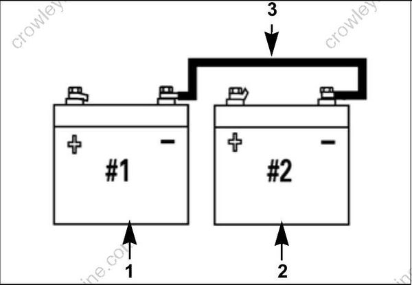
- Starting battery (primary)
- Accessory battery (secondary)
- Cable connecting negative (–) battery terminals
Battery and Switch Wiring Diagrams
One outboard: Battery disconnect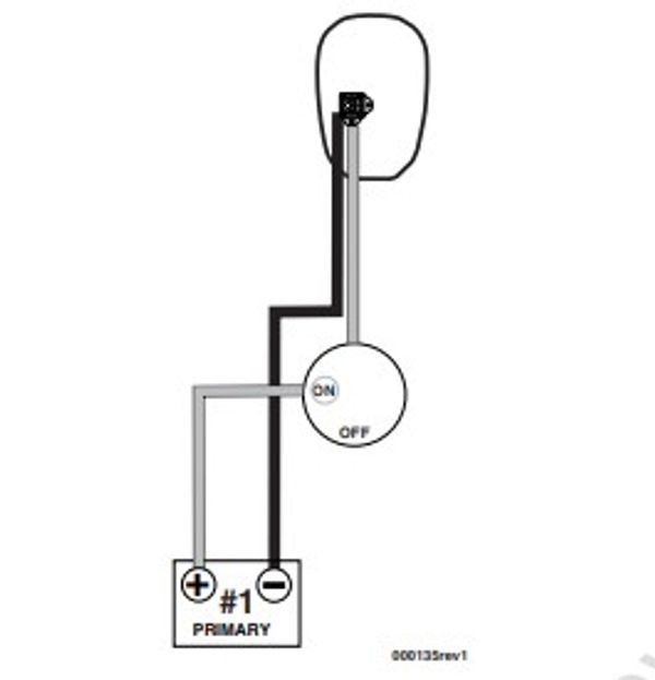
One outboard: One primary starting battery; one secondary battery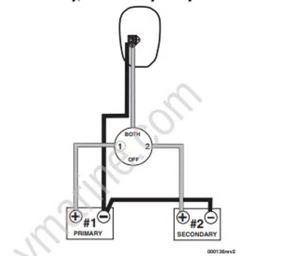
Two outboards: Two starting batteries for each outboard.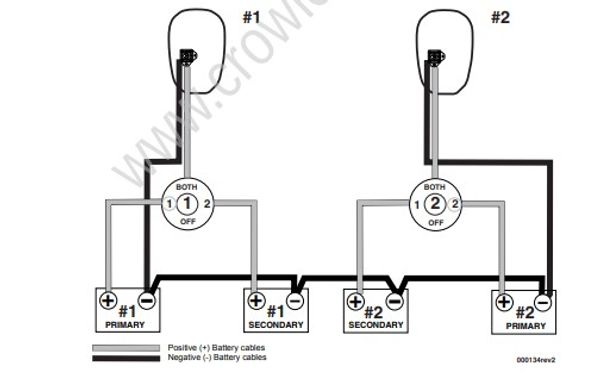
Positive (+) Battery cables
Negative (-) Battery cables
Fuel System Requirements
Overview
Boat fuel systems must meet minimum specifications to insure the proper delivery of fuel to the outboard.
The guidelines established by the ABYC and U.S. Coast Guard should always be followed.
- Permanent fuel tanks must be properly vented outside of the hull.
- Remote fuel tank gas fills must be grounded.
- Permanent fuel tank pickups should have the correct anti-siphon valve installed to prevent fuel flow if a leak occurs in the fuel distribution system. Refer to ABYC Standard H-24.
Fuel Hose
All fuel hoses must be designated as fuel hose and approved for marine use.
- Use only fuel lines (or copper tubing) that meet the outboard minimum I.D. requirement.
- “USCG Type A1” fuel hose must be used between permanent fuel tanks and motor well fittings on inaccessible routings.
- Use “USCG Type B1” for fuel hose routings in motor well areas.
- Permanently installed fuel hoses should be as short and horizontal as possible.
- Use corrosion-resistant metal clamps on permanently installed fuel hoses.
- Multi-outboard applications require separate fuel tank pickups and hoses. (A fuel selector switch may be used for “kicker” motors as long as it has enough flow capacity for the larger outboard.)
Fuel System Primer
Outboards require a priming system capable of refilling the fuel system after periods of non-use.
Primer bulbs that meet the outboard's minimum inside diameter fuel line requirements are used on most outboards.
Install the primer bulb in the fuel supply hose as follows:
- The primer bulb should be installed in an accessible location.
- The arrow on the primer bulb must point in the direction of fuel flow.
- The fuel primer bulb must be positioned in the fuel supply hose so the primer bulb can be held with the arrow pointing “up” during priming.
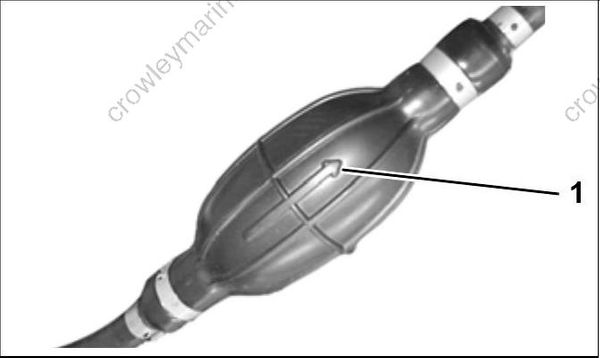
- Arrow indicates direction of fuel flow
An alternative to a primer bulb is a U.S. Coast Guard approved marine primer pump. Electric primer pumps offer the convenience of outboard priming from a dash-mounted momentary switch.
Fuel Filters
Boat-mounted fuel filters and water-separating fuel filter assemblies must meet the required fuel flow and filter specification. The filter must be mounted to a rigid surface above the “full” level of the fuel tank and accessible for servicing.
Fuel Filter Assembly, P/N 174176, meets all requirements for a water-separating fuel filter.
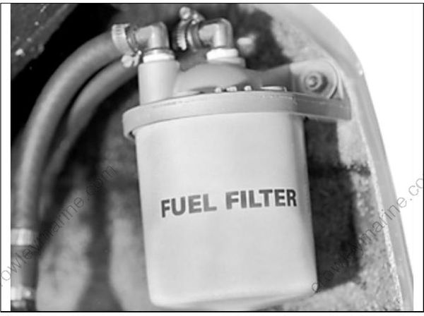
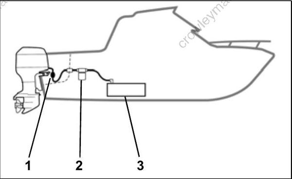
Typical Fuel Supply Configuration
- Primer bulb
- Water separating fuel filter
- Anti-siphon valve, in fuel pick-up of tank
IMPORTANT: Avoid using “in-line” fuel filters. The filter area and flow characteristics may not be adequate for high horsepower outboards.
Portable Fuel Tanks
Do not use portable fuel tanks for outboards larger than 115 HP. Inadequate fuel flow to high horse power outboards can result in serious powerhead damage.
Outboard Fuel System Recommendations

Cable and Hose Installation
Before installation, identify all required wiring, cables, and hoses:
- Throttle and shift cables
- Instrument harnesses
- Battery cables and switches
- Fuel supply hose
- Primer bulb or primer pump
Determine whether any additional wiring or hoses will be needed for accessory gauges or batteries:
- Speedometer pick-up hose
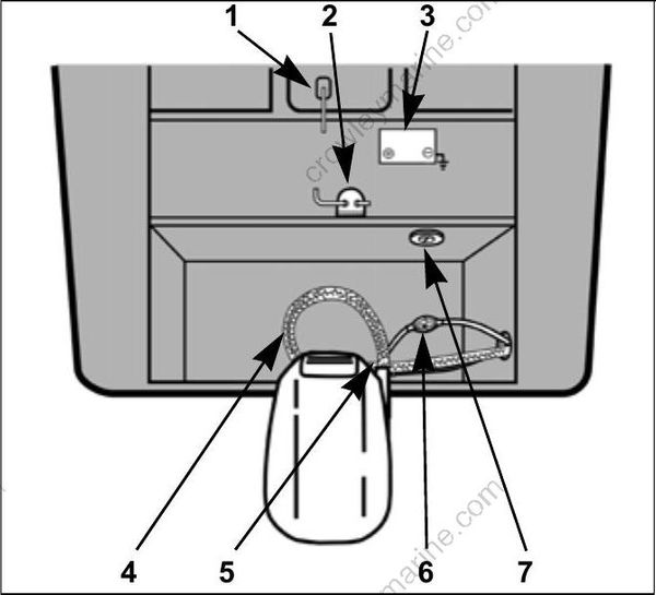
Typical outboard installation
- Anti-siphon valve
- Water separating fuel filter
- Starting battery
- Flexweave protective sleeve
- Access cover
- Primer bulb
- Battery switch
Cable and Wire Harness Routing
Improper installation and routing of outboard controls could wear, bind, and damage components, causing loss of control.
Remote control cables, wiring, and hoses must follow a similar path into the lower motor covers. Select the best routing for the specific application.
All cables, wiring, and hoses must be long enough to provide adequate slack. Check clearances at all possible combinations of trim angles and steering positions.
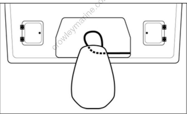
Typical Small Splash Well
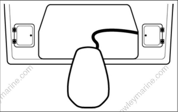
Typical Large Splash Well
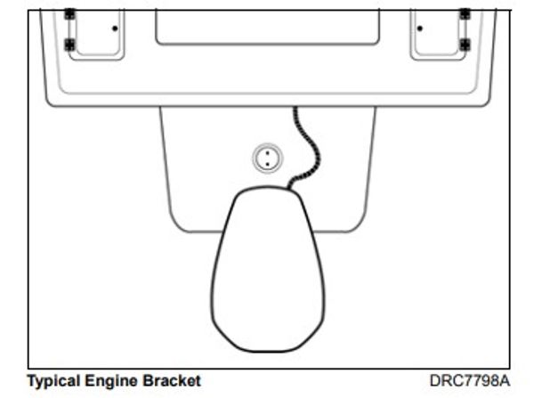
Typical Engine Bracket
Make sure all cables, wiring, and hoses have been identified and fitted to the appropriate lengths. Refer to OUTBOARD RIGGING on p. 44.
Battery Cables
Evinrude outboards are equipped with premium quality battery cables that should be long enough for most installations.
When routing battery cables, be sure to:
• Use the most direct path to route the battery cables to the battery or battery switch.
Fuel Hose
Route fuel hoses with enough slack to allow the primer bulb arrow to point “up” during use.
Install the primer bulb with the arrow pointing in the direction of fuel flow to the outboard.
Connect the fuel supply hose fitting to the fuel connector fitting on the outboard.
Oetiker Clamp Servicing
Use Oetiker† clamps for making hose connections. These clamps provide corrosion resistance, minimize the potential for abrasion of rigging components, and provide solid, permanent connections.
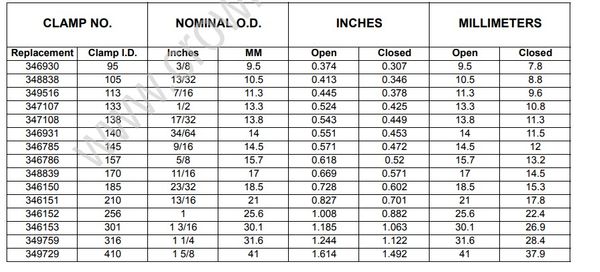
The selection and installation of an Oetiker clamp is essential in the proper sealing of hose connections. The clamp identification numbers appear in millimeters on the side of the clamp, near the top of the ear. Refer to Oetiker Stainless Steel Stepless Clamps chart for actual dimensions.
DO NOT re-use Oetiker clamps. Fuel leakage could contribute to a fire or explosion.
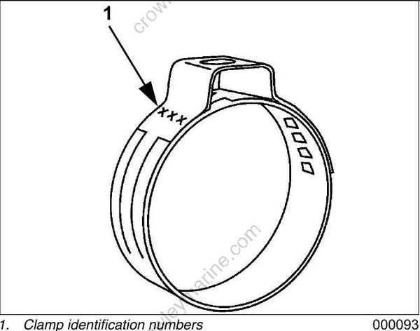
- Clamp identification numbers
The nominal size of the clamp should be chosen so that, when it is assembled on the connecting part, the outside diameter of the hose lies approximately in the middle of the clamping range of the clamp.
Oetiker Stainless Steel Stepless Clamps
Clamp Installation
A constant stress should be applied to close the ear clamps. This method ensures a positive stress on the hose and does not result in excessive compression or expansion of the band material.
IMPORTANT: Use only Oetiker recommended tools to close Oetiker stepless clamps.
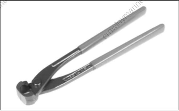
Oetiker pincers are available in the Evinrude/Johnson Genuine Parts and Accessories Catalog.
- Position correct size clamp over hose.
- Install hose on fitting.
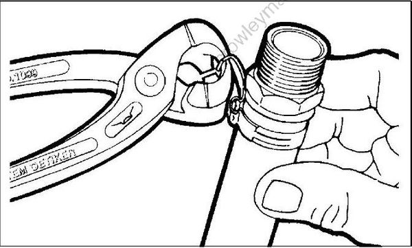
- Close clamp ear fully with Oetiker pincers (pliers).
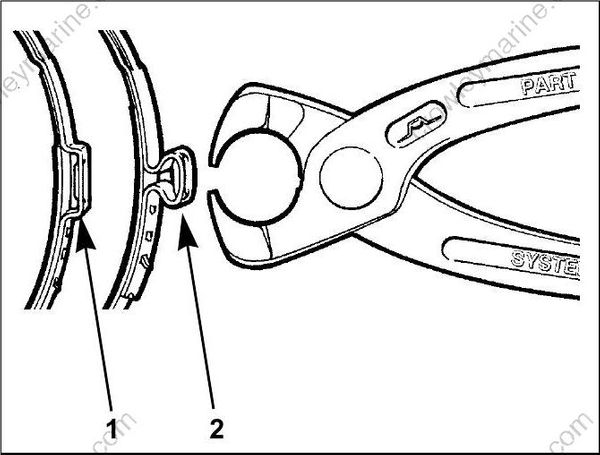
- Open clamp
- Closed clamp
Clamp Removal
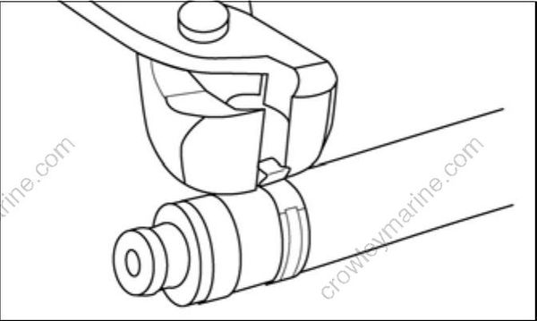
Method 1: Position Oetiker pincers across clamp ear and cut clamp.
Method 2: Lift end of stepless clamp with screwdriver.
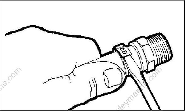
Method 3: Use Oetiker pincers (pliers) to grip clamp. Pull clamp off of connection and discard.
Control Cable Identification
IMPORTANT: Control cable function must be identified before rigging outboard.
Identify each control cable:
- Put the control handle into NEUTRAL position. The throttle cable casing guide will retract completely and the shift cable casing guide will go to the midpoint of its travel.

- Shift cable casing guide extended to midpoint
- Throttle cable casing guide retracted
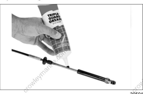
Extend the control cables and lubricate them with Triple-Guard grease.
OUTBOARD INSTALLATION
Hull Preparation
Maximum Capacity
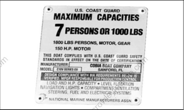
Do not overpower the boat by installing an outboard that exceeds the horsepower indicated on the boat’s capacity plate. Overpowering could result in loss of control.
Before installing outboard:
- Refer to the boat manufacturer's certification label for maximum horsepower rating.
- Refer to ABYC Standards to determine the maximum horsepower capacity for boats without certification labeling.
Mounting Surface
Inspect transom surface prior to drilling mounting holes.
- The transom should meet ABYC Standards.
- The transom must be flat.
- The transom angle should be approximately 14 degrees.
- Check transom strength and height.
The stern brackets must contact the flat surface of the transom. Modify trim that prevents the stern brackets from resting against the transom surface. Do not modify stern brackets.
