

FUEL SYSTEM TESTS
Use caution when working on any pressurized fuel system. Wear safety glasses and work in a well ventilated area. Extinguish all smoking materials and make certain no open flames or ignition sources exist. Before starting any fuel system service, carefully relieve fuel system pressure. Failure to properly relieve fuel system pressure can result in spraying fuel and/or excessive fuel spillage during servicing. Fuel is flammable and can be explosive under certain conditions.
Fuel System Pressure Test
Relieve fuel system pressure. Refer to Relieving Fuel System Pressure on p. 158.
Protect against hazardous fuel spray. Before starting any fuel system service, carefully relieve fuel system pressure.
After relieving fuel system pressure, install a 0 to 60 psi (0 to 415 kPa) Fuel Pressure Gauge, P/N 5007100 or equivalent, to the fuel pressure test fitting.
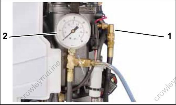
- Test fitting
- Fuel pressure gauge
START outboard and check pressure. System pressure should be 28 to 32 psi (193 to 220 kPa).
Shut OFF outboard. Monitor pressure gauge. Pressure should not drop below 15 psi (103 kPa).
IMPORTANT: If outboard does not run, prime fuel system and crank outboard; check circulation pump operation; check fuel system pressure.
Results:
Normal pressure:
- Observe pressure reading after outboard is shut OFF
- Refer to Lift Pump Pressure Test on p. 155
Pressure drops after outboard is shut OFF:
- Check for leaking fuel injector.
- Check for leaking pressure regulator.
- Check for external fuel system leak.
High pressure:
- Replace vapor separator.
Low pressure:
- Check fuel supply to fuel lift pump. Refer to Lift Pump Vacuum Test on p. 156. Higher vacuum readings indicate restrictions in the fuel supply. Repair or replace as needed.
- Restricted fuel filter/water separator assembly.
- Lift pump not supplying enough fuel to vapor separator. Refer to Lift Pump Pressure Test on p. 155.
- If the above tests are good and vapor separator remains full of fuel, check for damaged circulation pump. Replace vapor separator assembly.
No pressure:
- Check electrical circuit and ground connections for circulation pump.
- If voltage is present and pump does not run, repair connection or replace vapor separator assembly.
Relieve fuel system pressure before removing fuel pressure gauge. Refer to Relieving Fuel System Pressure on p. 158.
Vapor Separator Vent Check
Monitor the vapor separator vent hose. No fuel or a trace of fuel is acceptable. Excessive fuel dis charge indicates a vapor separator vent malfunction. Monitor vent for presence of fuel during testing. Temporarily install clear tubing for monitoring. Replace vapor separator if the venting of fuel is continuous.
Fuel Injector Pressure Test
Disconnect the battery cables at the battery.
Remove vapor separator assembly. Refer to Vapor Separator Removal on p. 160.
IMPORTANT: Perform test with injector mounted to cylinder head.
Seal injector outlet fitting with a cap, such as Plug, P/N 315391, and a tie strap.
Connect a 0 to 30 psi (0 to 207 kPa) pressure tester to the inlet fitting. Secure with tie strap, P/N 320107.
Pressurize the injector to 30 psi (207 kPa). Pres sure must hold for at least five minutes.
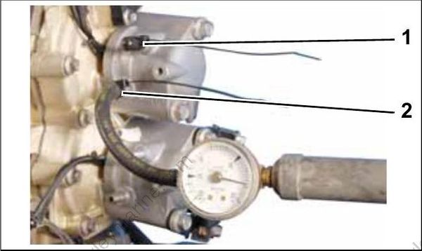
- Outlet fitting
- Inlet fitting
Refer to FUEL DELIVERY TESTS on p. 108 for additional test procedures.
Fuel Injector Resistance Test
Disconnect the battery cables at the battery.
Use a digital multimeter to measure the injector coil resistance.
| Fuel Injector Coil Resistance |
|---|
| 2 to 3 Ω @ 72°F (22°C) |
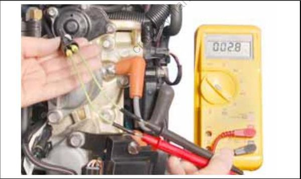
Use a digital multimeter with appropriate adapter leads to measure the injector circuit resistance.
Measure resistance between pin 2 of injector connector and the appropriate pin location of EMM connector. Refer to engine wiring diagram for specific EMM connector pin location for the injector circuit being tested.
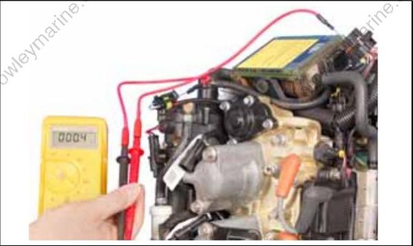
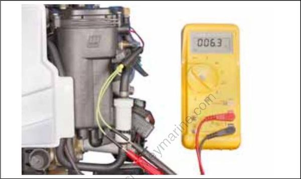
Circulation Pump Resistance Test
Disconnect the battery cables at the battery.
Use a digital multimeter with appropriate adapter leads to measure the fuel pump circuit and coil resistance.
| Fuel Pump Resistance |
|---|
| 2 to 8 Ω @ 77°F (25°C) |
Lift Pump Pressure Test
Install a 0 to 15 psi (0 to 103 kPa) Fuel Pressure Gauge. Tee into the fuel supply line before the fuel filter.
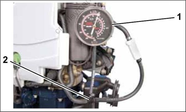
- Fuel pressure gauge
- Tee fitting
Pressure should stabilize at a reading greater than 2 psi (14 kPa).
Results:
Normal pressure:
- Perform the Lift Pump Vacuum Test on p. 156. Make sure no air leaks or restrictions exist in the fuel supply hose or boat fuel system.
Low pressure:
- Check pulse hoses and fittings for restrictions.
- Perform the Lift Pump Vacuum Test on p. 156. Make sure no air leaks or restrictions exist in the fuel supply hose or boat fuel system.
- Check fuel flow through fuel lift pump. Use fuel primer bulb to force fuel through pump.
No pressure:
- Check pulse hoses and fittings restrictions.
- Check fuel flow through fuel lift pump. Use fuel primer or primer bulb to force fuel through pump.
- Momentarily prime or squeeze primer bulb to check gauge operation.
- Check pulse hose and fittings for restrictions.
Lift Pump Vacuum Test
Confirm fuel supply to the fuel lift pump.
Temporarily install a vacuum gauge, T-fitting, and 8 in. (20.3 cm) of clear vinyl hose between the fuel supply hose and fuel lift pump (inlet). Secure connections with tie straps to prevent fuel or air leaks.
IMPORTANT: Do not use fuel primer bulb, manual fuel primer, or electric fuel pump primer to restart outboard. A positive pressure in the fuel supply could damage some vacuum gauges.
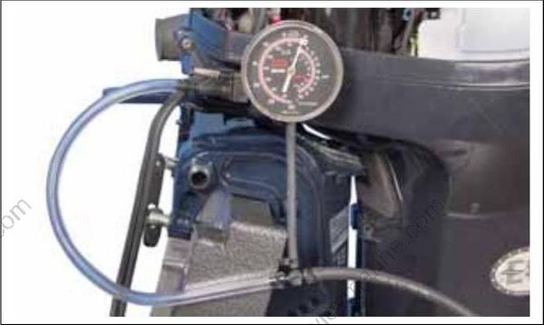
START outboard and run at FULL THROTTLE for at least two minutes. Monitor clear vinyl hose for the presence of air. Air bubbles indicate a faulty hose, connection, or fuel tank pick-up. Repair, if necessary, before proceeding.
There should be no air or vapor bubbles visible in the clear hose. The maximum inlet fuel vacuum should not exceed 4 in. Hg. (13.5 kPa) at the inlet to the fuel lift pump under any operating conditions (IDLE to WOT).
A higher vacuum indicates an excessive restriction in the fuel supply. Repair as needed. Refer to Fuel System Requirements on p. 29 for fuel supply component requirements.
Lift Pump Diaphragm Test
Perform this test only if a damaged pump is suspected. This test does not confirm the performance of the internal fuel pump check valves.
Remove the fuel inlet and outlet hoses from the fuel pump housing.
Attach gearcase pressure tester to the fuel outlet. Apply 3 psi (20 kPa). Replace lift pump if pump fails to hold pressure.
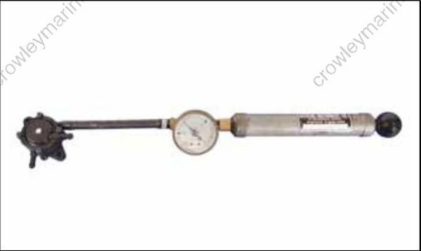
Attach gearcase vacuum tester to the fuel inlet. Apply 3 in. Hg. (-10 kPa). Replace lift pump if pump fails to hold vacuum.
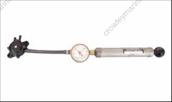
Anti-Siphon Valve Test
Remove anti-siphon valve from fuel tank. Install adapter fittings and a 36 in. (91.4 cm) length of clear hose to the inlet side (tank end) of valve.
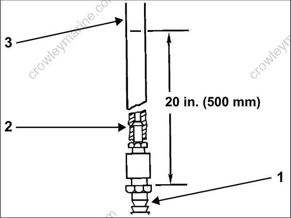
- Anti-siphon valve
- Adapter fitting
- Clear hose
Fill clear hose with water to a height of 20 in. (500 mm). Water must NOT flow through valve. An occasional drip is acceptable. Replace valve if water drips continuously.
Increase height of water to 25 in. (630 mm). Water should flow through valve as water level reaches 25 in. (630 mm). Replace the anti-siphon valve if test results are different.
