

Step 1: ELECTRICAL AND IGNITION
Thoroughly clean the crankshaft and flywheel tapers with Cleaning Solvent™ and let dry.
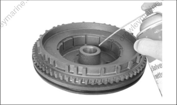
Align the flywheel keyway and install flywheel.
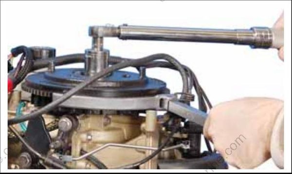
Coat the threads of the flywheel nut with Triple-Guard grease.
Install the washer and nut and tighten to a torque of 100 to 110 ft. lbs. (135 to 150 N·m).
Replace recoil starter.
IMPORTANT: Check ignition timing after flywheel removal or replacement. Refer to TIMING ADJUSTMENTS on p. 135.
Step 2: TIMING ADJUSTMENTS
Timing Pointer
The timing pointer on Evinrude E-TEC 25 – 30 HP models is not adjustable.
Timing Verification
Use Evinrude Diagnostics software to synchronize the mechanical timing of the outboard with the electronic timing of the EMM.
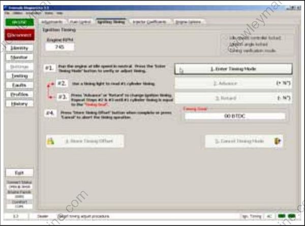
Ignition Timing Screen
Check ignition timing after any of the following procedures:
- Powerhead replacement
- Crankshaft replacement
- Flywheel removal or replacement
- CPS replacement
- EMM replacement
- EMM software replacement (reprogramming)
IMPORTANT: Make sure the timing pointer is set and the outboard reaches operating temperature before making any timing adjustments.
TPS Calibration
Use Evinrude Diagnostics software to tell the EMM what throttle position sensor voltage is when the throttle plates begin to open.
Remove the air silencer.
On the Settings screen of the diagnostics soft ware, click the “Set TPS Calibration” button.
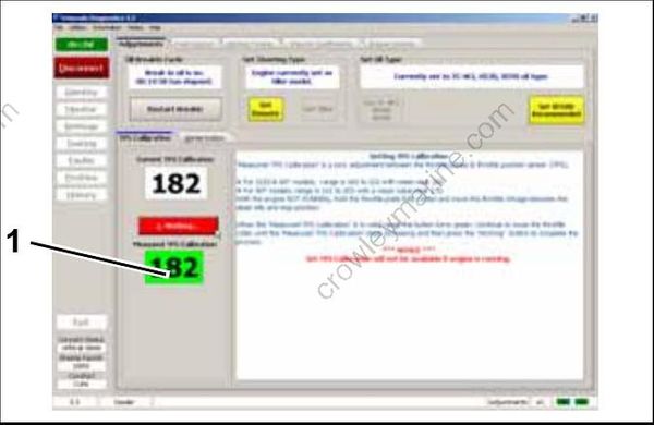
- TPS Calibration button
While holding the throttle plates closed, advance the throttle linkage until it stops. The “Measured TPS Calibration” field on the screen will increase.
Click the “Working” button in the software to calibrate the TPS.
Install the air silencer.
Set TPS Calibration after replacing or adjusting any throttle body or throttle linkage parts.
Step 3: ELECTRIC STARTER SERVICING
Starter Removal
IMPORTANT: Do not clean the starter drive while the starter motor and drive are installed on the powerhead. The cleaning agent could drain into the starter motor, washing dirt from the drive into the starter bearings and commutator.
Disconnect the battery cables at the battery.
Remove lower motor covers. Refer to Lower Cover Removal on p. 75.
Remove the starter positive (+) cable from post on starter.
Remove three starter mounting screws. Remove the starter.
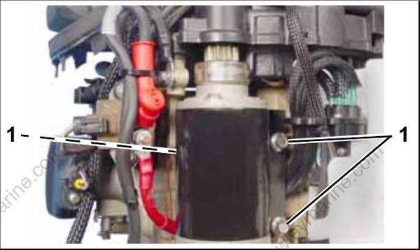
- Screws
