

TILT/TRIM RELAY TEST
The tilt and trim (TNT) module contains the circuitry and relays required for power trim and tilt operation.

- Tilt and trim module
The tilt and trim switch provides B+ input to green/white or blue/white wire of the TNT module.
Operation
The relay activates when B+ input from the switch is supplied to terminal 86 of the internal relays.
Terminal 87a connects to ground (B–).
Terminal 87 connects to B+.
Terminal 30 connects TNT motor.
Terminals 87a and 30 are connected when relay is not activated. This supplies ground (B–) connection to TNT motor.
Terminals 87 and 30 are considered “normally open.” B+ is applied to terminal 30 when relay is activated. This supplies ground B+ connection to TNT motor.
Refer to Tilt and Trim Module Diagram..
Test Procedure
Make sure red and black wires are connected to 12 V battery power supply.
Set voltmeter to 12 VDC scale. Connect test leads to terminals “A” and “B” of TNT motor connector.
Use a wire jumper to alternately connect B+ to terminals “1” and “2” of tilt and trim switch connector.
The meter must indicate battery voltage (12 V) with B+ connected to either terminal.
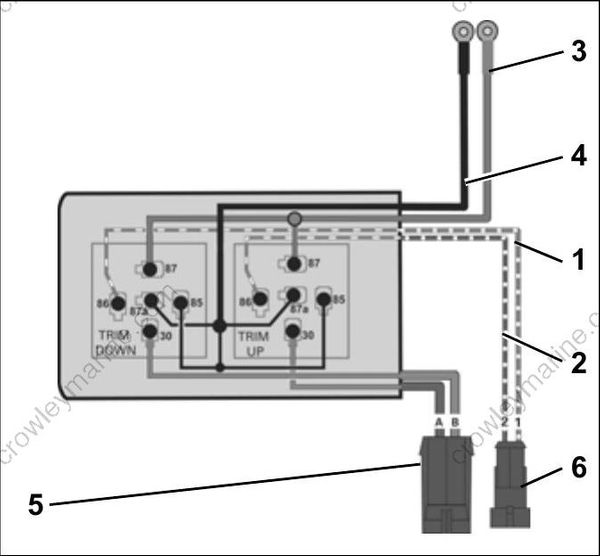
Tilt and Trim Module Diagram
- Green/white wire
- Blue/white wire
- B+, red wire
- B–, black wire
- TNT motor connector
- TNT switch connector
